-
Analysis of the causes of signal attenuation in optical splitters
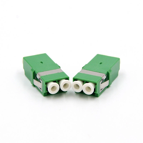
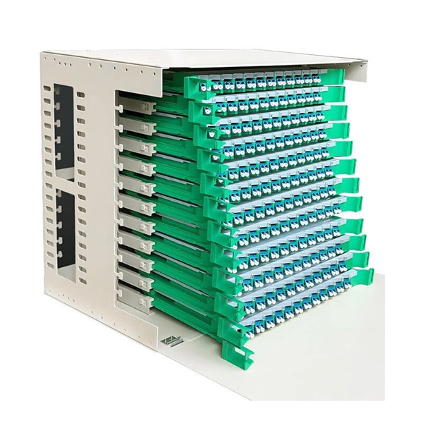
In the context of beam splitters, attenuation can occur due to several factors, including absorption, reflection, and scattering. Understanding how beam splitters affect signal attenuation and polarization is essential for optimizing systems in telecommunications, imaging, and laser applications. In the. Fiber optic splitters distribute optical power from one input fiber to multiple output fibers through either fused biconical taper (FBT) coupling or planar lightwave circuit (PLC) waveguide structures. Their performance depends on optical symmetry, waveguide integrity, and mechanical stability of. · Signal Attenuation: The loss of signal strength as it travels through the fiber can lead to poor quality communication. By careful processing, couplers that were bidirectional were made. So a 2:2 coupler would take the signal from one fiber on one side and split it between the two fibers on the.
[PDF Version]
-
Increase the light output power of the optical module
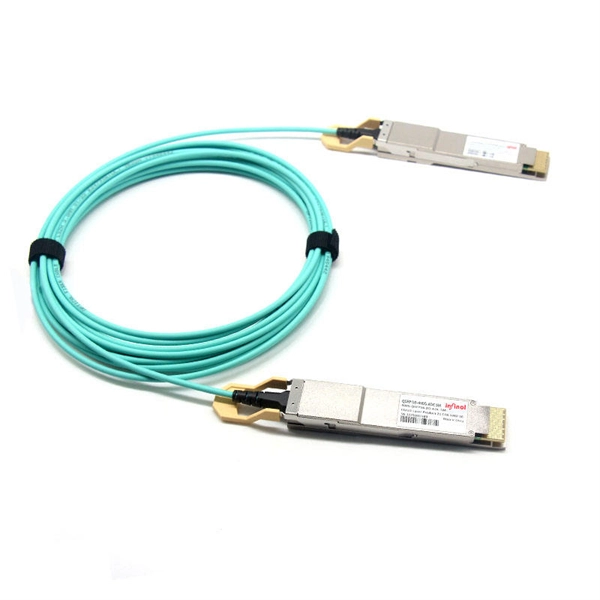
An optical amplifier is a device which receives some input signal light and generates an output signal with higher optical power. Typically, inputs and outputs are laser beams (very rarely other types of light beams), either propagating as Gaussian beams in free space or in a fiber. At the receiver end, the optical signals are reconverted into electrical. In this guide, we will explain what optical signal strength is, how to check it on Cisco IOS using the command line, and how to troubleshoot common light level issues. Assume the. This application note gives a short introduction to optical modules and the need of an optimized power tree in them and then concentrates on the use cases and benefits of four-switch and inverting buck-boost converters inside optical modules.
-
Huawei 5680 optical module emits light
The optical module is faulty. SmartAX MA5680T: Access product manuals, HedEx documents, product images and visio stencils. Get your solutions if you have met some problems. Explore the essential query commands for efficiently managing and troubleshooting the Huawei MA5680T, a versatile and robust telecommunications access platform. Learn how to retrieve vital information, configure settings, and diagnose network issues using these commands. Indicates the MIB object ID of the alarm. Does anyone have any troubleshooting suggestions for this device? Here's what I've checked so far: In case it matters, here are. Description: Original Huawei optical line terminal for FTTx networks, supporting GPON/EPON, IPTV, VoIP, and enterprise services. The Huawei OLT MA5680T is a large-capacity optical line terminal widely deployed in FTTx networks.
-
How to determine light attenuation of red light using an optical power meter
Optical attenuation compares input and output power on a logarithmic scale. When powers are in linear units, the loss in decibels is: Attenuation (dB) = 10 × log10 (Pin / Pout) If the link length L is provided, the attenuation coefficient is: Coefficient (dB/km) =. Analyze optical power drop across fibers and links. Switch units, lengths, and calculation modes easily. Needed when attenuation is an. Optical power, required for measuring source power, receiver power and, when used with a test source, loss or attenuation, is the most important parameter and is required for almost every fiber optic test. Backscatter and wavelength measurements are the next most important and bandwidth or. Optical power meters are a key element in the optimization and maintenance of such optical networks and of their components. But, for designers, just starting to work in the fiber-optic design space, measuring attenuation can seem like a monumental task.
[PDF Version]
-
Which end of the optical module receives light
At the receiving end, the module converts the light back into electrical signals for processing. Lasers are used for longer distances and higher speeds, while LEDs. It is processed by an internal driver chip, which drives a semiconductor Laser Diode (LD) or Light Emitting Diode (LED) to emit a modulated optical signal at the corresponding rate. The key components inside an optical module include: Laser Diode. The Transmitter Optical Sub Assembly (TOSA) is responsible for the emission of light. LD is suitable for long-distance, high-speed transmission, while LED is used for short-distance, low-speed applications.
-
High-precision light source for optical power meter used in Sudan s 5G base station
An optical power meter (OPM) is a device used to measure the power in an signal. The term usually refers to a device for testing average power in systems. Other general purpose light power measuring devices are usually called,, power meters (can be sensors or ), or lux meters. A typical optical power meter consists of a , measuring and display. The sens.
-
Is the R-port on the optical module for receiving or transmitting light
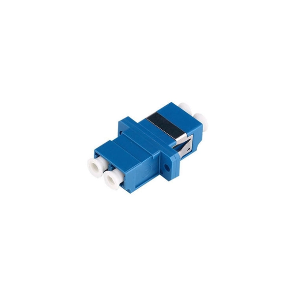
ROSA is the component inside the receiver side of the SFP port. The ROSA is responsible for receiving the optical signal transmitted by the TOSA of the opposite end's transceiver and converting it back to an electrical signal so that the communication equipment can understand it. Optical modules typically have an electrical interface on the side that connects to the inside of the system and an optical interface on the side that connects to the outside. The integrated optical transceiver module is the core device of optical communication, which completes the optical-electrical/electrical-optical conversion of optical signals. We'll cover everything from physical form factors to spectral characteristics, modulation formats. Ensures a proper connection between the optical module and the optical port of the device. It exists only on an SFP optical module.
[PDF Version]
-
Requirements for Optical Module Circuit Boards
Since they are used to interconnect electronic devices, optical module PCBs are designed to meet several requirements, such as supporting high-speed data transmission, dissipating heat, and enabling hot-swapping. Optical module PCB design demands exceptional accuracy to ensure stable and. This guide serves as an in-depth resource for engineers, designers, and project managers involved in the development of optical module PCBs. 1 mm in thickness, with most designs comprising ≤12 layers. These materials lower energy loss and help high-frequency work better.
-
Huawei optical module has no light
This problem can be detected by checking whether the light port is on, then checking whether the light module parameters such as wavelength, speed and transmission distance match, and then checking whether the gateway is configured and whether the VLAN is the same. Check the model of the faulty optical module. If it is not a Huawei-certified optical module, replace it with a Huawei-certified optical module. If the optical module is installed on a GE port, run the display interfaceGigabitEthernet x/x/x command to view port information when the optical module. Optical modules are widely used in switches, network interface cards (NICs), routers, and other communication devices. Q1: The Optical transceiver and two pairs of multi-mode fiber jumper are used to connect Huawei Switch and Hua3 switch. The optical transceiver is not bright A: on the premise that the equipment is working properly, we first need to eliminate the problem of the optical fiber line itself, and then. When using Opticomm you want to have a WAN light not a DSL light. You connect to it via ethernet cable, not DSL cable.
[PDF Version]