-
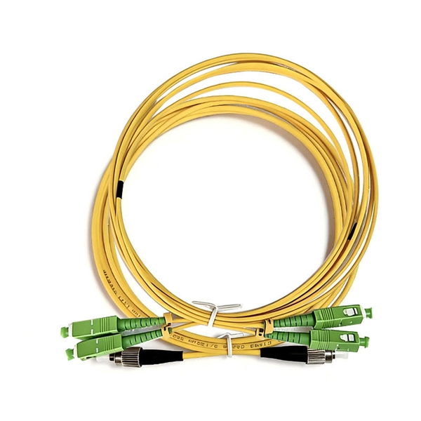
Working principle of 10 Gigabit fiber optic patch cord
The functioning of a fiber optic patch cord relies on its construction. It consists of a core with a high refractive index, enveloped by a coating featuring a lower refractive index. This assembly is fortified using aramid yarns and encased within a protective jacket. These cables, also known as fiber optic patch cables or jumpers, are designed to transmit information as pulses of light, offering unparalleled speed, bandwidth, and immunity to electromagnetic interference compared to traditional copper cables. As network demands continue to explode, selecting the. Key factors to consider in the design of 10 Gigabit Ethernet networks are: The network topology, including operating distances, splice losses and numbers of connectors (i. Fiber optic patch cables are found almost everywhere; cable television networks (CATV), data centers, computer networks, and telephone networks.
[PDF Version]
-
Control Principle of Fiber Optic Sensors
Fiber optic current sensors work by detecting changes in light as it interacts with a magnetic field created by an electrical current. This section provides a detailed look at fiber optic sensors. What Is a Sensor? Learn all about the principles, structures, and features of eight sensor types according to their detection principles. Radiation absorption creates electronic excited states that are trapped by localized defects for extended periods of. Brief theory of sensing principle, fabrication method, applications, advantages and disadvantages of the different fiber‐optic sensors, are addressed. Optical fiber sensors (OFSs) have emerged as essential tools in the monitoring of physical, chemical, and bio-medical parameters in harsh situations due to their high sensitivity, electromagnetic interference (EMI) immunity, and long-term stability.
[PDF Version]
-
Working principle of dual-axis fiber optic collimator
The basic working principle is that the fiber's end face is placed at or near the focal point of a lens. Light exiting the fiber spreads out; if positioned correctly relative to the lens, the lens converts that diverging cone into a beam with minimal divergence (a collimated . Fiber optic collimators (also called fiber-optic collimators) are crucial optical components that convert the diverging output from an optical fiber into a collimated (parallel) beam, or conversely focus light from free space into a fiber. They can also be used in reverse to focus light into a fiber. In principle, a simple collimation lens (see Figure 1) is sufficient for that purpose. However, the fiber end has to be firmly fixed at a distance from the lens which is approximately equal. Thorlabs offers a variety of fiber collimation and coupling solutions.
[PDF Version]
-
Principle of Diaphragmless Fiber Optic Ultrasonic Sensors
A compact optical fiber ultrasonic sensor based on Fabry-Perot (FP) interferometer is proposed and demonstrated. The sensor consists of a single-mode fiber (SMF) spliced with a short section of.
-
Working Principle of Fiber Optic Temperature Sensor in Kyrgyzstan
Fiber optic temperature sensors operate based on changes in light properties as it travels through the fiber. Temperature measurement can be achieved through various methods, including: However, these traditional systems often suffer from limited immunity to electromagnetic. Fiber optic temperature sensors have emerged as a critical technology in various industries, providing precise temperature measurements with distinct advantages over traditional temperature sensors. Unlike conventional sensors, they do not need electrical power at the sensing point, thereby making them inherently safe in volatile environments.
-
Working principle of optical beam splitters
These beamsplitters are made by coating the hypotenuse of dual prisms with a partially reflecting material and joining them together using optical or epoxy cement. A beam splitter or beamsplitter is an optical device that splits a beam of light into a transmitted and a reflected beam. It is a crucial part of many optical experimental and measurement systems, such as interferometers, also finding widespread application in fibre optic telecommunications. a laser beam) into two (or sometimes more) beams, which may or may not have the same optical power (radiant flux).
-
Principle of Optical Fiber Communication Refraction
Refraction, or the change in the direction of light as it changes speeds passing from one material into another, is a key component in fiber-optic transmission. An optical fiber can be understood as a dielectric waveguide, which operates at optical frequencies. Following image depicts a bunch of fiber optic cables. The principles that cause an object in water to. Optical fibers are thin glass rods that use the properties of light reflection and refraction to transmit data over long distances. Sinceeach mode travels at a different velocity on the fiber, an optical bit launched into the. Fiber-optic communication is a method of transmitting data from one point to another by sending infrared light pulses through an optical fibre.
-
Applications of ADSS optical fiber cables
AFL-ADSS® (All-Dielectric Self-Supporting) fiber optic cable is a non-metallic cable which supports its own weight without the use of lashing wires or messenger cables, typically installed in overhead applications along power distribution or transmission rights-of-way. In the realm of aerial fiber optic infrastructure—where cables must withstand harsh weather, high voltages, and mechanical stress— ADSS (All Dielectric Self-Supporting) fiber optic cables stand out as a game-changer. The self-supporting idea is literal here. The result is that they can be hung in a straight line between poles or towers with no additional metallic. One such innovation is the ADSS cable, a fiber optic solution designed to meet the demands of modern networking while providing exceptional performance and reliability.
-

Optical fiber cables are a type of display media
A fiber optic cable is a high-speed data transmission medium that carries information as light pulses through strands of glass or plastic fibers. Each strand contains a core and cladding that use total internal reflection to guide the light signal across long distances with minimal. An optical fiber, or optical fibre, is a flexible glass or plastic fiber that can transmit light from one end to the other. The fiber which is used for optical communication is waveguides made of. It's not just the case that fiber optic cables are better, though. The process relies on a principle called Total Internal Reflection. In this blog post, we will explore the different types of optical fiber cables, their benefits, and their applications in different industries.
-
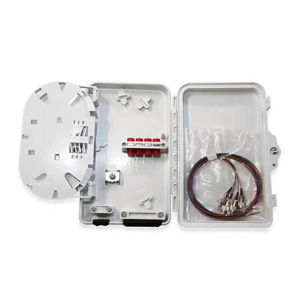
Pigtails are a type of optical fiber
A fiber optic pigtail is a short optical fiber cable that has a connector on one end and an exposed (unterminated) fiber on the other. The connector end plugs into devices like transceivers or patch panels, while the bare end is typically fusion spliced to a fiber optic cable. They are the bridge between fiber optic cables in the field and the equipment or patch panels that manage them. By combining factory-installed connectors with spliced bare fiber, pigtails ensure that network installers can create. Executive Summary: A fiber optic pigtail is one of the most commonly specified yet least understood components in structured cabling. Get the wrong connector type, the wrong polish, or skip proper fusion splicing technique—and you're looking at elevated signal loss, increased back reflection, and a. A fiber pigtail is typically a fiber optic cable with one end factory pre-terminated fiber connector and the other exposed fiber.
[PDF Version]
-
The Development History of Fiber Optic Acoustic Sensors
Fiber-optic interferometric acoustic sensors were first proposed for US Navy applications 36 years ago. This paper will review the origin, development and deployment of these sensors. Future applications will also be discussed. This content is available for download via your institution's subscription. To access this item, please sign. Fiber‐optic sensor technology has experienced tremendous growth since its early beginnings in the 1970s with early laboratory demonstrations of fiber‐optic gyros and acoustic sensors and the introduction of the first commercial intensity and spectrally based sensors. These early efforts were. The Design Of Fiber Optic Sensors For Measuring Hydrodynamic. Navy's effort to develop sensors that used optical fiber to detect targets at sea offers a window into how a technology goes from basic research to production.
[PDF Version]