-
Working principle of 10 Gigabit fiber optic patch cord
The functioning of a fiber optic patch cord relies on its construction. It consists of a core with a high refractive index, enveloped by a coating featuring a lower refractive index. This assembly is fortified using aramid yarns and encased within a protective jacket. These cables, also known as fiber optic patch cables or jumpers, are designed to transmit information as pulses of light, offering unparalleled speed, bandwidth, and immunity to electromagnetic interference compared to traditional copper cables. As network demands continue to explode, selecting the. Key factors to consider in the design of 10 Gigabit Ethernet networks are: The network topology, including operating distances, splice losses and numbers of connectors (i. Fiber optic patch cables are found almost everywhere; cable television networks (CATV), data centers, computer networks, and telephone networks.
[PDF Version]
-

Switches are all 10 Gigabit optical
To implement different 10GbE physical layer standards, many interfaces consist of a standard socket into which different physical (PHY) layer modules may be plugged. PHY modules are not specified in an official standards body but by (MSAs) that can be negotiated more quickly. Relevant MSAs for 10GbE include (and related X2 and XPAK), and. When choosing a PHY.
-
10 Gigabit Ethernet card optical module not connected to fiber optic cable
Troubleshooting SFP+ link issues in 10 GbE networks requires attention to module type, match of speed and wavelength, clean fiber connections, correct configuration, thermal management, and equipment compatibility. You can quickly resolve SFP+ Module connectivity issues by following a systematic optical transceivers troubleshooting process. Check for common connection problems, such as link failures or modules not recognized. Check compatibility between the optical module and switch Most switch brands have specific compatibility requirements. During network upgrades, many enterprise users encounter a common issue: after replacing 10G broadband lines or inserting 10G SFP+ optical modules, the switch still fails to operate at full 10G bandwidth or even fails to recognize the modules. We've listed the five most common ones. First of all, let's briefly recap what SFP and SFP+ stand for. SFPs – short for 'small form-factor pluggable' – are compact, hot-pluggable devices.
[PDF Version]
-
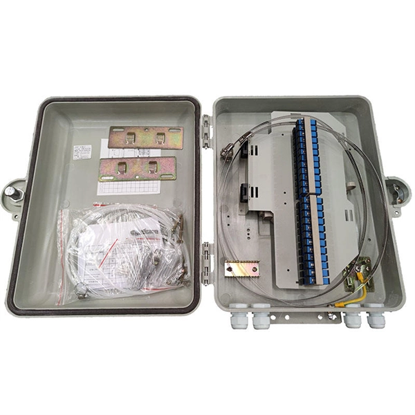
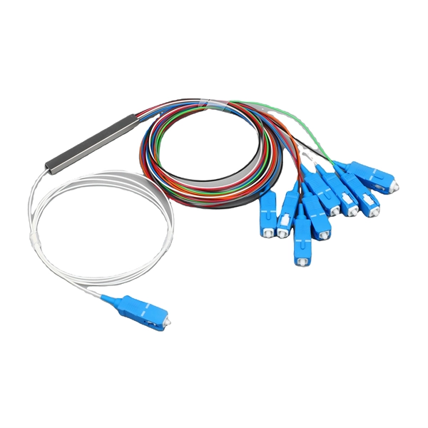
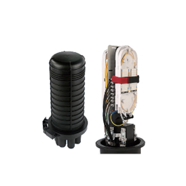
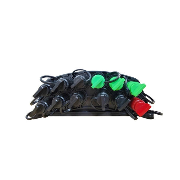
Coupler connection to optical fiber
Fiber optic couplers can either be passive or active devices. Passivefiber optic couplers are said to be passive as no power is required for operation. They are simple fiber optic components that are used to redirect light waves. Passive c. Fiber optic couplers can either be passive or active devices. Passivefiber optic couplers are said to be passive as no power is required for operation. They are simple fiber optic components that are used to redirect light waves. Passive couplers either use micro-lenses, graded-refractive-index (GRIN) rods and beam splitters, optical mixers, or spl. Types of fiber optic couplers include splitters, combiners, X-couplers, trees, and stars, which all include single window, dual window, or wideband transmissions. Fiber optic splitterstake an optical signal and supply two outputs. They can further be described as either Y-couplers or T-couplers. 1. Y-couplershave equal power distribution, meaning t. When specifying optical couplers you should consider the fiber optic cable, the coupler type, signal wavelength, number of inputs and outputs, as well as insertion loss, splitting ratio, and polarization dependent loss (PDL).
[PDF Version]
-
Price of power communication fiber optic cable connection
Fiber optic cable installation costs between $1,500 and $7,000 for your home, with prices varying by cable length and installation method. The installation type you choose and the layout of your property determine the total labor and materials needed for your project. You should account for permit. Whether you're running fiber to a home or a data center, here's exactly what contractors are charging in 2026. fiber projects, we've assembled current material rates, labor burdens, and hidden fees.
-
Are gigabit optical modules prone to failure
Gigabit optical transceivers and 10 Gigabit optical transceivers are an essential part of modern network communication, but they will inevitably encounter some failures during use. However, the failure of optical modules is a common problem during use, which not only affects the network quality, but also may lead to network interruption. In this article, we will discuss some of the common failure methods of gigabit single-mode optical fiber modules. Power Supply Failure Power supply failure is one of the most common failure methods of gigabit. Modules operating at 100G, 200G, or 400G inherently present higher failure probabilities compared to 1G, 10G, or 40G predecessors, largely due to increased design and process complexity. For example, a 40G optical transceiver essentially bundles four 10G channels operating simultaneously; a failure. A single optical module failure can disrupt training jobs worth hundreds of thousands of dollars in compute time.
[PDF Version]
-
Fiber optic connection to router cannot be used
The most common causes of this are loss of power to the fiber terminal (ONT) or an unplugged network cable. The other end of this cable should be plugged into the active wall jack or indoor. The process to connect fiber optic cable to router requires careful attention to detail, but I'll walk you through every critical step with the precision and clarity you deserve. This comprehensive guide combines industry standards with field-tested practices to ensure you achieve a rock-solid. Fiber optic internet represents the pinnacle of internet connectivity, utilizing strands of glass or plastic to transmit data as pulses of light. Unlike traditional copper-based cable or DSL, fiber offers significantly higher speeds, lower latency, and greater reliability. The fiber. This morning my ISP upgraded my Internet connection from a standard coaxial cable and Cisco modem to a fiber optic cable and Hitron modem Model Name NOVA-2004. Despite multiple attempts, the Archer AX6000 v1.
[PDF Version]
-
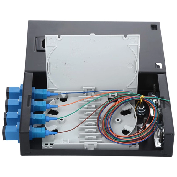
Repair after fiber optic cable fuse failure
This article outlines five specific steps for repair: 1) Identify the break; 2) Cut out the damaged section; 3) Strip the cable; 4) Trim the fiber ends; 5) Test the repair. DIY fiber optic cable repair kits are increasingly popular for those who prefer home repairs. When fiber cables sustain damage, specialized repair techniques help restore connectivity and maintain data integrity. Whether you're a network technician, IT professional, or telecom operator, you'll find practical steps, tools, and tips to restore. By understanding these key elements and following the outlined steps, you can effectively repair fiber optic cables and maintain the high-performance network necessary for today's demanding communication needs. Proper use of these tools and. There are two primary techniques for joining broken fibers or installing new connectors. The choice depends on required performance, budget, and application. It's ideal for long-haul.
[PDF Version]
-
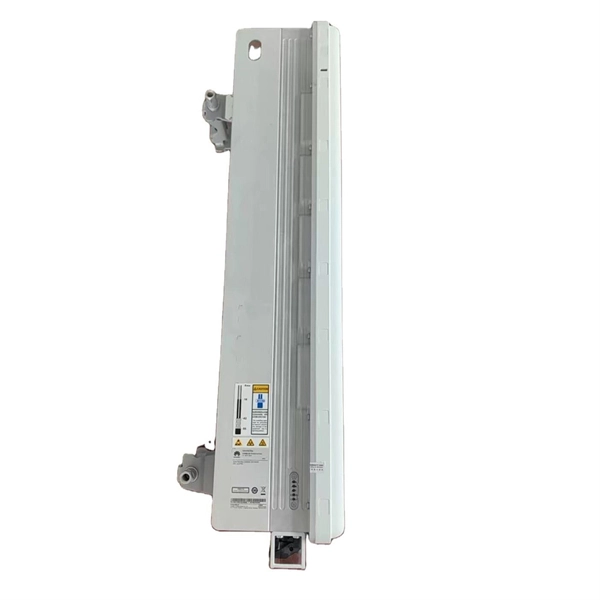
Huawei optical module power failure alarm
The optical module is faulty or not securely installed. If the transmit optical power is abnormal, replace. Run the display interface transceiver command to check whether any alarm information has been generated for the optical module. Alarm information: LOS Alarm RX LOL Warning information: If the LOS alarm is displayed, the local optical interface does not receive signals from the remote. The transmit power of the AP's optical module fell below the lower threshold. Indicates the MIB object ID of the alarm. During use, reading optical module information helps understand its real-time operating status, enabling faster troubleshooting of link abnormalities.