-
Relay Protection Circuit Diagram Numbering Rules
This handbook covers the code of practice in protection circuitry including standard lead and device numbers, mode of connections at terminal strips, colour codes in multicore cables, dos and donts in execution. Also principles of various protective relays and schemes including special protection. For power grid systems, ANSI and IEEE functional number codes dictate the use and restrictions of both the devices themselves, as well as the functions of those devices within the scope of a circuit. These devices include switches, disconnects, circuit breakers, generators, and motors. One is given in ANSI Standard and uses a numbering system for various functions. The functions are supplemented by letters where amplification of the function is required.
-

Relay Protection Test Wiring Method
One approach to test the total protection system is to use primary injection techniques (see appendix H) that trigger protective relays and lockout relay, trip circuit breakers, and initiate annunciations and indications. If applicable, documentation is required detailing how verified protection segments overlap to ensure there is not a gap. The purpose of this Standard Work Practice (SWP) is to standardise and describe the method for testing of Ergon Energy protection relays for commissioning purposes. This SWP should be interpreted in conjunction with Standard for Substation Protection (V1. From a technician's perspective, master the unique skill of testing protection. When the transformer wiring type is Y/Y (Y0), the test wiring is very simple: when testing phase A, the tester IA is connected to the phase A of the high voltage side, and the tester IB is connected to the phase a of the low voltage side. After the neutral line of the high and low voltage sides is. Function: Use electronic components like transistors to perform switching. Applications: Frequency, undervoltage, and overcurrent protection.
[PDF Version]
-
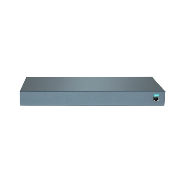
Diagram of trough-type cable tray accessories
Legrand continues to be an innovator in cable management solutions and is proud to introduce Cablofil Trough Tray, a cable management system designed to maximize network reliability and minimize lifec.
-
Electrical diagram of main distribution box
This AutoCAD DWG file provides a complete Electrical Single Line Diagram (SLD) of the MSB, along with a detailed panel layout, including circuit breakers, busbars, instruments, and feeders. Understanding the wiring diagram of the main electrical panel is crucial for anyone who wants to have a basic understanding of how electrical systems work. To understand how a breaker box works, it is helpful to. Power distribution panel is used for utilization of equipment. Power supply is received from LT panel and distributed to the outgoing feeders for utilization.
-
No supports are allowed at the cable tray connection points
Support spacing for cable trays must align with the manufacturer's instructions, as outlined in NEC 392. Generally, standard trays require supports every 6 to 10 feet, while heavy-duty, long-span trays can handle distances of up to 20 feet between supports. This is a description of how to select, install, and support these metal or plastic frames, on which electrical wires are installed. Here's what you need to know: Cable Types: Only use. Cable trays can be part of a planned cable management system to support, route, protect, and provide a pathway for cable systems. Power, low voltage control, data, or telecommunications wiring distribution systems can be used with cable trays. Cable trays can provide a safe component of a power, low voltage.
-
Fiber optic router has signal but no internet connection
Restarting your router, checking your modem connection, and resetting network settings often resolve the problem quickly. A quick restart of your router and modem can often re-establish the. Unraveling the mystery behind a strong signal but no internet connection is essential for both individuals and businesses relying on a seamless online experience. This article aims to delve into the common causes of this issue, provide troubleshooting tips, and empower readers with the knowledge. If your router shows it's connected but you can't access the internet, don't panic—this is a common issue with simple fixes. When issues like signal loss, slow speeds, or intermittent connectivity arise, systematic troubleshooting is key. Try these steps: Fiber Jack GFLT100 The Fiber Jack connects your home to the GFiber network. The good news: it is almost always fixable without calling your ISP.
[PDF Version]
-
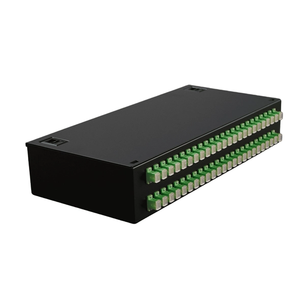
Coupler connection to optical fiber
Fiber optic couplers can either be passive or active devices. Passivefiber optic couplers are said to be passive as no power is required for operation. They are simple fiber optic components that are used to redirect light waves. Passive c. Fiber optic couplers can either be passive or active devices. Passivefiber optic couplers are said to be passive as no power is required for operation. They are simple fiber optic components that are used to redirect light waves. Passive couplers either use micro-lenses, graded-refractive-index (GRIN) rods and beam splitters, optical mixers, or spl. Types of fiber optic couplers include splitters, combiners, X-couplers, trees, and stars, which all include single window, dual window, or wideband transmissions. Fiber optic splitterstake an optical signal and supply two outputs. They can further be described as either Y-couplers or T-couplers. 1. Y-couplershave equal power distribution, meaning t. When specifying optical couplers you should consider the fiber optic cable, the coupler type, signal wavelength, number of inputs and outputs, as well as insertion loss, splitting ratio, and polarization dependent loss (PDL).
[PDF Version]
-
Dual busbar connection switching
Three-phase power with currents of up to 5 Amps per phase can be carried, measured and switched by means of the double busbar model. Compare single-bus and double-busbar switchgear: cost, flexibility, reliability, maintenance, and which bus arrangement suits what facility. Busbar switchgear helps control and distribute electricity safely inside a power system. It uses metal bars called busbars to connect incoming and outgoing. Here, we provide an overview of common substation busbar configurations—Single Bus, Main and Transfer, Double Breaker/Double Bus, Ring Bus/Ring Main, and Breaker and a Half. In case of failure of either of the transformers, busbars, cables or their associated switchgear, a changeover option between the two will be at. In Simple words, a bus-bar is a common connection point or a node for multiple incoming and outgoing circuits such as power lines or feeders. Understanding the difference between an isolator and a circuit breaker. The configuration in back-to-back or front-to-front completes the extensive range of panel types and options available.
[PDF Version]
-
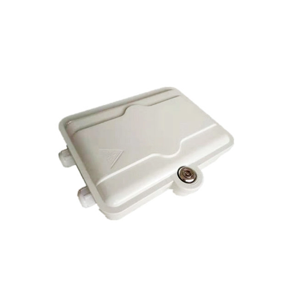
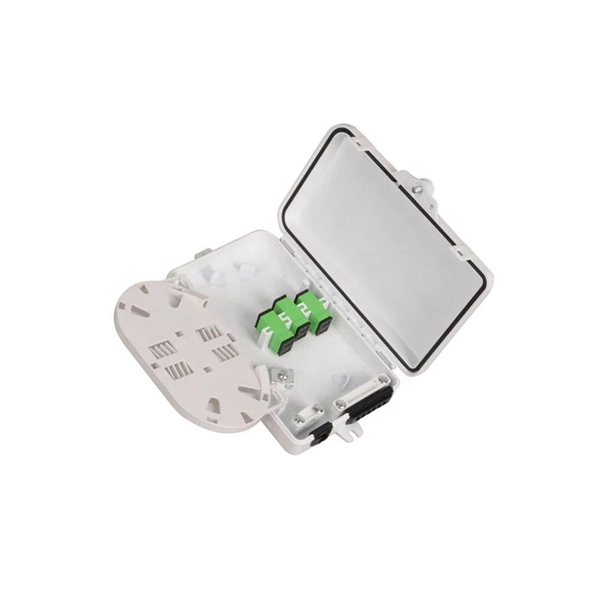
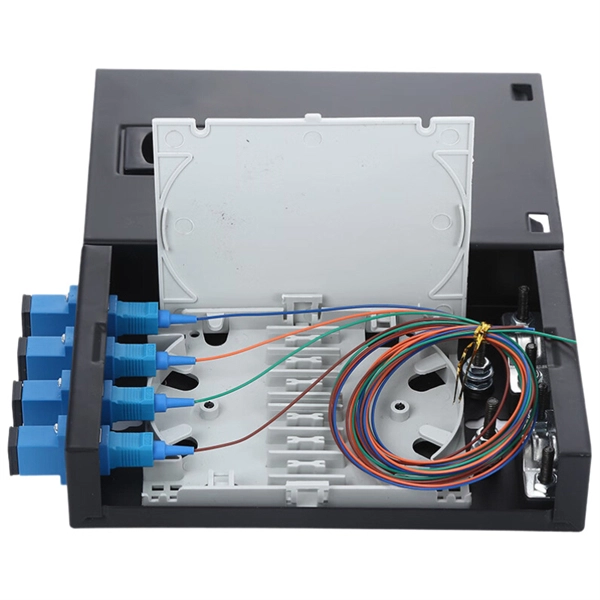
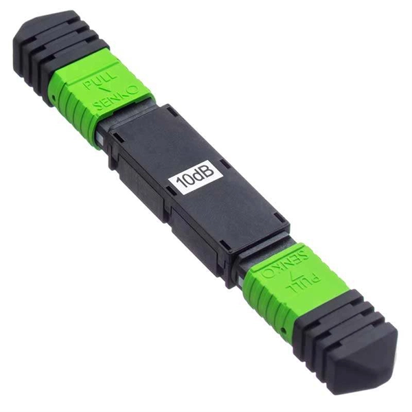
Fiber Optic Cable Loop Connection Method
A fiber optic ring network is a physical or logical network topology where devices (usually switches) are connected in a closed-loop using fiber optic cables. Each node is connected to two other nodes, forming a ring-like structure. This design ensures data can travel in both. Fiber optic technology has superior speed and time, so it has been accepted in many sectors. Loopback connectors are at the heart of this technology, the most conspicuous being the MPO (Multi-fiber Push On) loopback connector, which is essential in performance assessment. In as much as this guide. 40. FO-VC2 JOINT USE - VERICAL MIDSPAN CLEARANCES 48. APPENDIX A - COVER SHEET / TOC 52. Butterfly-shaped optical fiber cables, also known as ribbon fiber optic cables, are a type of fiber optic cable that contains multiple fibers within a single flat ribbon.
-
Schematic diagram of trough-type cable tray
Legrand continues to be an innovator in cable management solutions and is proud to introduce Cablofil Trough Tray, a cable management system designed to maximize network reliability and minimize lifec.