-
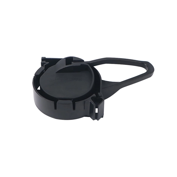
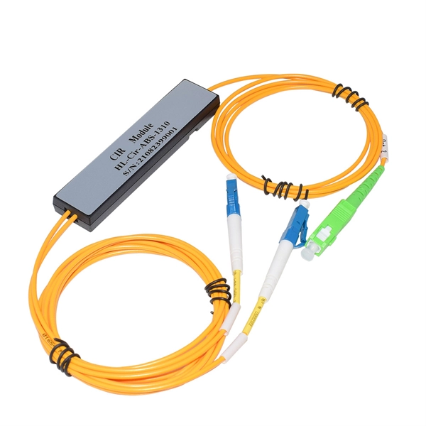
Is it okay to pick up the beam splitter outside
A beam splitter or beamsplitter is an optical device that splits a beam of light into a transmitted and a reflected beam. It is a crucial part of many optical experimental and measurement systems, such as interferometers, also finding widespread application in fibre optic telecommunications. DesignsIn its most common form, a cube, a beam splitter is made from two triangular glass which are glued together at their. Beam splitters are sometimes used to recombine beams of light, as in a. In this case there are two incoming beams, and potentially two outgoing beams. But the amplitudes. For beam splitters with two incoming beams, using a classical, lossless beam splitter with Ea and Eb each incident at one of the inputs, the two output fields Ec and Ed are linearly related to the inputs thro. Beam splitters have been used in both and in the area of and and other fields of. These include: •. In quantum mechanics, the electric fields are operators as explained by and. Each electrical field operator can further be expressed in terms of representing the wave behavior a.
[PDF Version]
-
Principles and Product Design of Optical Fiber Communication
Optical Fiber Communication (OFC) revolutionizes modern telecommunications, enabling rapid data transfer across long distances with minimal signal loss. This comprehensive review explores OFC's historical evolution, core principles, components, and versatile applications. Kanade Department of Electronic-Science, P. College of ASC, Pravaranagar, India fPublished. The digital communication techniques discussed so far have led to the advancement in the study of both Optical and Satellite communications. Light acts as a carrier wave and can be modulated to carry information. Higher bandwidth (extremely high data transfer rate).
-
Requirements for Relay Protection Design
The IEEE standard for protection relays refers to a collection of guidelines developed by the Institute of Electrical and Electronics Engineers. This document provides recommendations, background and philosophy on relay protection that is not available in M07. They are intended to quickly identify a fault and isolate it so the balance of the system continue to run under normal conditions. For professionals working in utilities, industries, or renewable energy systems, understanding these standards is not optional—it is essential. This handbook covers the code of practice in protection circuitry including standard lead and device numbers, mode of connections at terminal strips, colour codes in multicore cables, dos and donts in execution.
-

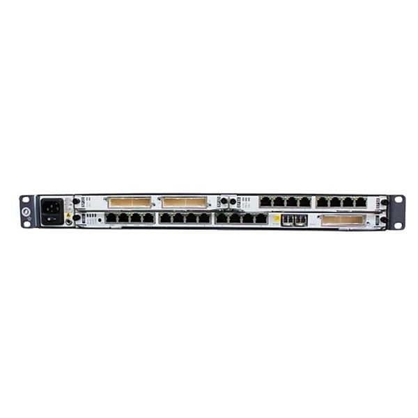
WDM Fiber Optic Communication System Design
This lesson demonstrates the basic features of a typical WDM optical communication system and shows the basic design steps with OptiSystem. The performance of the system will be shown and compared. In fiber-optic communications, wavelength-division multiplexing (WDM) is a technology which multiplexes a number of optical carrier signals onto a single optical fiber by using different wavelengths (i. Single mode fiber is favored over Multimode fiber for long-distance communication. Firstly, the WDM optical. While fiberoptic technology resulted in a significant increase in a network's "bandwidth," or the amount of information that the network could send, tbe creation of the Internet resulted in an even greater demand for bandwidth. As demand for network capacity increased, service providers exhausted.
-
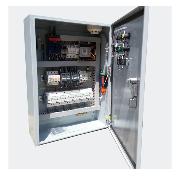
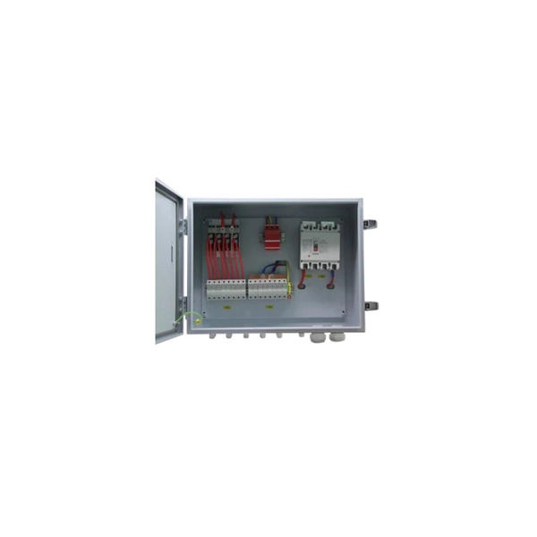
Emergency Circuit Design for Distribution Boxes
Size emergency and standby circuits with NEC 700/701, IEC 60364-5-56, UPS/generator transfer paths, and real voltage-drop examples. On a recent plan review, the riser looked clean: NEC 700 emergency lighting, a listed transfer switch, copper conductors, and breakers sized. Emergency and standby power systems are designed to provide an alternate source of power if the normal source of power, typically the electric utility service, should fail. Reliability of these types of systems is critical and good design practices are essential. Classification of Emergency and. Emergency system circuits supply power to critical life safety loads such as emergency lighting, fire alarm systems, fire pumps, smoke control systems, and essential communication and control circuits. Correct wiring design for emergency system circuits is essential to maintain power integrity. The National Electrical Code (NEC) Section 700. Under no. Another is to limit what qualifies as an “emergency load,” so the emergency system powers only what is needed to save human life (Fig.
[PDF Version]
-
Moroccan fiber optic cable manufacturing plant
Moroccan company FBR Cables inaugurated a new fiber optic and network cable manufacturing plant in Berrechid on Monday, a project valued at MAD 200 million (USD 21. 7 million), Moroccan outlet SNRT News reported. Morocco's Industry and Trade Minister Ryad Mezzour attended the launch. Morocco has taken a significant step toward strengthening its digital infrastructure with FBR Cables' launch of a major new industrial platform aimed at boosting domestic fiber optic cable production. 7 million) industrial investment aimed at strengthening domestic production capacity.
-
How many days does it typically take for the relay protection system of a power plant to recover
The magnetic system in induction disc overcurrent relays is designed to detect overcurrents in a power system and operate with a pre-determined time delay when certain overcurrent limits have been reached.OverviewIn, a protective relay is a device designed to trip a when a is detected. The first protective relays were electromagnetic devices, relying on coils operating on moving par. Electromechanical protective relays operate by either, or. Unlike switching type electromechanical with fixed and usually ill-defined operating voltage thresholds. Electromechanical relays can be classified into several different types as follows: "Armature"-type relays have a pivoted lever supported on a hinge or knife-edge pivot, which carries a moving contact. These relays may.
-
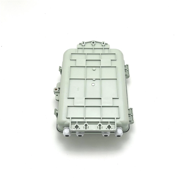
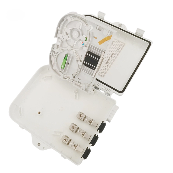
What s the coating on the outside of the distribution box
In order to improve the waterproof performance of industrial power distribution box, manufacturers will apply a layer of special waterproof coating on the surface of the box. Usually, rubber sealing rings or sealants are used for sealing to effectively prevent the intrusion of rainwater, sand and dust. In addition, for some special interfaces. Our powder-coated steel distribution box is designed to offer a rugged, reliable, and affordable solution for indoor electrical distribution systems. Constructed from high-quality cold-rolled steel and finished with a durable powder coating, this enclosure provides excellent protection against. The groove contours of electronic distribution boxes and the very narrow grooves of micro-distribution housings are seamlessly sealed with the sealing foams of the polyurethane-based FERMAPOR K31 or the silicone-based FERMASIL product families.
[PDF Version]
-

Fiber optic cable design reserve length
Standard/default length is 2 inches (reference), as produced by most label manufacturers. Marking details are based on MIL-STD-130 and will be legible and permanent. • Fiber optic cables are often custom cut to match required lengths for each cable run, or you can order a reel matching your total length and cut segments yourself. It's advisable to include a safety buffer when ordering, with an additional 10% being common practice, despite careful measurement of. Fiber optic network design refers to the specialized processes leading to a successful installation and operation of a fiber optic network. To calculate teh total number of fiber strands that will be required for the fiber optic cable installation, many people makes the mistake of underestimating the total. All lengths are calculated in a base unit, then converted. Reel count is ceil (Total ÷ ReelSize), and the rounded order length equals Reels × ReelSize. (FOA) was founded in 1995 to help develop the workforce to build the fiber optic networks to support a rapid expansion in communications and the Internet.
[PDF Version]
-
Relay Protection Design Guidelines
This handbook covers the code of practice in protection circuitry including standard lead and device numbers, mode of connections at terminal strips, colour codes in multicore cables, dos and donts in execution. This document supplements PJM Manual 07 which contains the minimum design standards and requirements for the protection systems associated with the bulk power facilities within PJM. The IEC standard for relay coordination provides clear guidelines and methodologies to ensure that protective relays work in harmony to isolate only the faulty section of the system while keeping the rest. Protective relays and devices have been developed over 100 years ago to provide “last line” of defense for the electrical systems.