-
How much splitter loss is used to calculate optical power
Insertion loss tells you how much weaker the signal becomes after passing through the splitter. Let's say you have a laser output at 0 dBm (which is 1 milliwatt of optical power). Factors influencing splitter loss include splitter. Instantly compute insertion loss, power at each subscriber port, and fade margin for PLC and FBT splitters — including dual cascade configurations. Covers GPON (1490 nm / 1310 nm), EPON, and RF video overlay (1550 nm). Add connector and splice quantities with realistic planning losses. Enable power budget to estimate received power and margin. Splitters are essential when you want one fiber line from a central office (like an ISP's headend or data center) to serve multiple homes or businesses.
-
Splitter Optical Path Loss
5 dB depending on splitter type. Optional: patch panels, attenuators, or extra components. Helps cover dirt, aging, and measurement tolerances. Calculate insertion loss for passive optical splitters in PON and distribution networks. Excess loss accounts for manufacturing imperfections, typically 0. DISCLAIMER: These calculators are provided for. Optical splitters play a crucial role in Fiber to the Home (FTTH) Passive Optical Network (PON) systems, efficiently distributing a single optical signal to multiple destinations. Common values: 2, 4, 8, 16, 32, 64. Understanding the types of splitters, their impact on network performance, and how to measure their losses ensures high-quality network operation and facilitates optimal splitter selection based on. Understanding optical splitter loss isn't just about plugging numbers into a calculator.
[PDF Version]
-
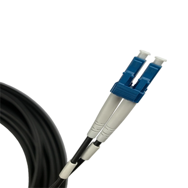
Optical cable termination optical loss
Optical fiber channel insertion loss is the decrease in optical power that occurs when an active transmitter is linked to an active receiver via terminated, optical fiber cables and patch cords and may include splice points and optical couplers. This Applications Engineering Note explains how different optical fiber termination methods impact the optical performance of telecommunications systems. Optical fiber cabling systems support various communications technologies that use digital as well as analog signaling. Gigabit Ethernet (GbE). Fiber optic joints or terminations - where cables are terminated - are made two ways: 1) connectors that mate two fibers to create a temporary joint and/or connect the fiber to a piece of network gear (left) or 2) splices which create a permanent joint between the two fibers (right).
-
Loss value of new optical cable 1310
Used to suggest a default attenuation value. Route length between active equipment. Usually higher loss than fusion splices. Include patch. At Aeliya Marine Tech, we strive to provide efficient and reliable shipping services to our customers worldwide. Please read the following information regarding our shipping policy: We offer various shipping options for each country, and the methods and costs are clearly indicated on all. Calculate link or channel loss and determine the supported applications and max lengths for the configuration. You can also select components to configure connections below. QuestTel shall have no liability for any error or damage of any kind resulting from the use of this document. Connector and Splice Losses: Every connector or splice in a fiber optic network introduces additional. This document outlines the specifications for a single-mode optical fiber and cable designed for use around the 1310 nm zero-dispersion wavelength, suitable for both the 1310 nm and 1550 nm regions, and compatible with analogue and digital transmission. It details the fiber's geometrical, optical.
[PDF Version]
-
Total loss during optical cable testing
Visual inspection identifies contamination, scratches, cracks, and endface defects that directly affect optical performance. Insertion loss testing measures the total optical loss of a fiber cable or. To be able to judge whether a fiber optic cable plant is good, one does a insertion loss test with a light source and power meter and compares that to an estimate of what is a reasonable loss for that cable plant. The estimate, called a "loss budget" is calculated using typical component losses for. At TREND Networks, we are frequently asked how much loss is allowed when conducting testing on fibre optic cabling. Unfortunately, it is not a simple answer and depends on several factors. So how do you determine acceptable loss? When testing fibre optic cabling, determining acceptable loss is. required. patchcords, with negligible fiber loss, the measured loss may be considered the loss of the connector mated to the reference connector.
[PDF Version]
-
Optical loss of an optical cross-connector
Reduce fixed losses, shorten distance, improve optics, or redesign the architecture. Compare wavelengths, distances, safety reserves, receiver limits, and operating headroom. Model optical links with practical engineering inputs fast. Review attenuation, splice, connector, and splitter effects. Check total loss, power margin, and feasibility clearly. Total Fiber Loss = Fiber Length × Attenuation Coefficient Total Connector Loss = Number of Connectors × Loss per. Fiber loss, also called fiber optic attenuation or attenuation loss, refers to the loss of signal between input and output. Many FTTH networks technically meet design specifications at deployment, yet experience gradual performance decline over time. Optical fibers are very small, on the size of a human hair, and require careful alignment of the fibers to get low loss. This is the loss of light signal, measured in decibels (dB), during the insertion of a fiber optic connector. absorption loss from impurities such as scratches and oil contamination.
[PDF Version]
-
Telecom Splitter Loss
Calculate insertion loss for passive optical splitters in PON and distribution networks. Power is divided equally among output ports. Excess loss accounts for manufacturing imperfections, typically 0. A deeper understanding of these. Use 2×N when two inputs feed the same distribution stage. Common values: 2, 4, 8, 16, 32, 64. 5 dB depending on splitter type. By dividing a single optical signal from a central Optical Line Terminal (OLT) into multiple outputs for Optical Network. It is an optical fiber tandem device with many input and output terminals, especially applicable to a passive optical network (EPON, GPON, BPON, FTTX, FTTH etc. ) to connect the MDF and the terminal equipment and to branch the optical signal.
-
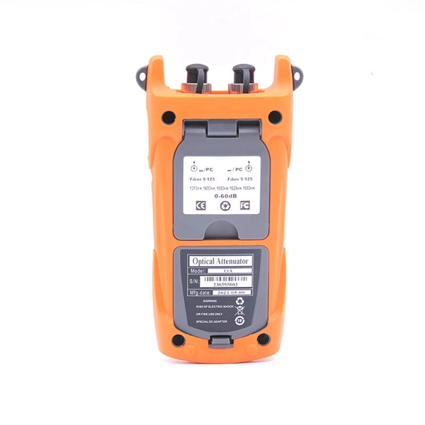
How to measure the loss rate of a beam splitter
To accurately measure optical splitter loss, utilize optical test equipment like power meters and spectral analyzers. Here's how: Measure the optical power at both the input and output ports of the splitter. This loss is primarily quantified as insertion loss, which measures the reduction in signal power due to the splitter's presence in the optical path. Common values: 2, 4, 8, 16, 32, 64.
-
Principle and Function of Base Station Optical Splitter
By dividing a single optical signal from a central Optical Line Terminal (OLT) into multiple outputs for Optical Network Terminals (ONTs) at users' homes, splitters eliminate the need for dedicated fibers to each residence—slashing infrastructure costs while scaling network reach. 📄 What is an Optical Splitter? An Optical Splitter, also known as a beam splitter, is a passive optical device that divides a single input optical signal into two or more output signals. Conversely, it can also combine multiple signals into one.
-
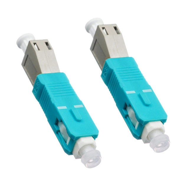
Does the optical splitter need an optical module and how is it connected
The optical transceiver module (like an SFP, SFP+, or XFP module) in the OLT is the laser source that generates the initial light signal. This high-power signal is transmitted down the single fiber. When it reaches the optical splitter, the signal is divided and sent. A fiber optic splitter is a passive optical component that divides a single incoming optical signal into two or more outgoing signals, or combines multiple incoming signals into one. Conversely, it can also combine multiple signals into one. It is a passive optical device with many input and output terminals, especially applicable to. An Optical Splitter (also known as a fiber optic splitter or beam splitter) is a passive optical power management device.