-
Principles of Optical Cable Junction Box Planning
OPGW cable joint box installation involves several key stages: selecting the appropriate location, preparing both the cable and the joint box, splicing fibers, and sealing the joint box properly. Adhering to these steps ensures optimal performance and longevity of the. The installation of an optical cable junction box is crucial in ensuring the integrity and performance of optical networks. As the demand for high-speed internet and reliable telecommunications increases, the. This guide optimizes the original text by delving deeper into the three pillars of fiber network longevity: the impact of splicing technology, the strategic selection of splice boxes, and the essential maintenance protocols needed to ensure sustained, high-speed functionality. The Critical Role. The Fiber Optic Association, Inc. (FOA) was founded in 1995 to help develop the workforce to build the fiber optic networks to support a rapid expansion in communications and the Internet. It determines where cables run, how signals are split and aggregated, and which technologies deliver data from central offices to end.
[PDF Version]
-
The first-stage optical path of the beam splitter is malfunctioning
In its most common form, a cube, a beam splitter is made from two triangular glass which are glued together at their base using polyester,, or urethane-based adhesives. (Before these synthetic, natural ones were used, e.g.) The thickness of the resin layer is adjusted such that (for a certain ) half of the light incident through one "port" (i.e., face of the cube) is and th.
-
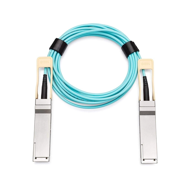
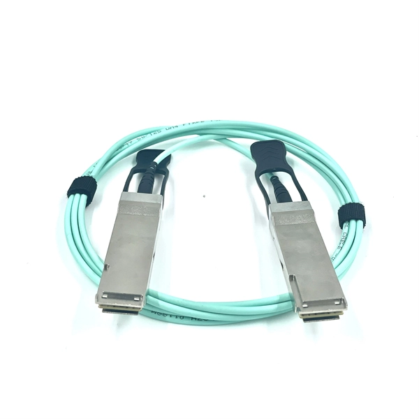
Multimode application scenarios for optical modules
We reviewed the technical specs, performance traits, and application scenarios of OM1, OM2, OM3, OM4, and OM5 multimode fibers. From OM1's foundational role to OM5's WDM innovation, each standard serves distinct needs. This article explains where multimode SFP transceivers are used, what problems they solve, and how to choose the right solution based on specific application scenarios. By focusing on practical use cases and deployment considerations, it aims to help network planners, system integrators, and IT. This case shares our company's optimization solution for the service stability issues caused by the deployment of 100G multimode optical modules in the live network of a computing power cluster enterprise. Unlike their single-mode counterparts, which are designed for long-distance communication, these modules shine in short-distance scenarios. Different lights enter the core at different angles of incidence, and are then continuously reflected between the core and the cladding for transmission. Differences Between Single-Mode and Multi-Mode.
[PDF Version]
-
Does passive optical device cause pollution
Artificial light at night (ALAN) is ever-present in modern society and has revolutionised our lives. Along with its many benefits, ALAN can have adverse effects that are studied across many fields, inclu.
-
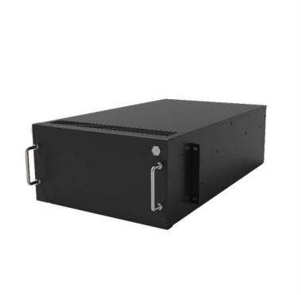
Optical Amplifier Uplink Device
Optical amplifiers are important in optical communication and laser physics. They are used as optical repeaters in the long distance fiber-optic cables which carry much of the world's telecommunication links.OverviewAn optical amplifier is a device that amplifies an directly, without the need to first convert it to an electrical signal. An optical amplifier may be thought of as a without an, or one in which. The principle of optical amplification was invented by on November 13, 1957. He filed US Patent US80453959A on April 6, 1959, titled "Light Amplifiers Employing Collisions to Produce Population Inversions".
-
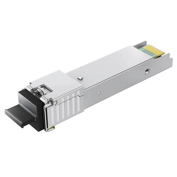
How to connect the SD signal in the 19 optical module
The unit accepts one SDI signal on a BNC connector and provides one optical output of this signal on an ST connector over single-mode cable with a 1310 nm wavelength. solution for virtually any conversion you could need. Mini Converters convert analog to digital, digital to analog, SDI to audio, audio to SDI, up, down and cross conversion, SDI distribution, and can even provide a sync generator for lockin all your video equipment to the same reference signal. These transceiver modules are hot-swappable input/output (I/O) devices that plug into 100BASE, 1000BASE and 10GBASE ports (for SFP+), which connect the module port with the fiber-optic or copper network. If the optical module is installed on a GE port, run the display interfaceGigabitEthernet x/x/x command to view port information when the optical module. When the optical module on an interface is faulty, you can run the display commands to view information about the optical module. The notices referring to your personal safety are highlighted in the manual by a safety alert symbol, notices referring only to property damage have no safety alert.
[PDF Version]
-

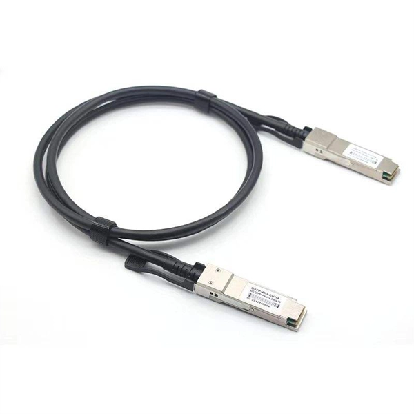
Switches are all 10 Gigabit optical
To implement different 10GbE physical layer standards, many interfaces consist of a standard socket into which different physical (PHY) layer modules may be plugged. PHY modules are not specified in an official standards body but by (MSAs) that can be negotiated more quickly. Relevant MSAs for 10GbE include (and related X2 and XPAK), and. When choosing a PHY.
-
Optical module receiving sensitivity is less than
Receive sensitivity defines the minimum optical power required to maintain an acceptable bit error rate (BER ≤ 1E-12) at specific data rates. It's a core parameter in optical transceiver specifications, indicating the module's capability to detect weak incoming signals. What Is BER? The bit error rate (BER) measures the data transmission precision within. In optical communication systems, sensitivity is a measure of how weak an input signal can get before the bit-error ratio (BER) exceeds some specified number. For example, SONET specifies that the BER must be 10 -10 or better. This level must fall within the receiver's power range.
-
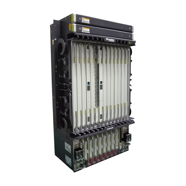
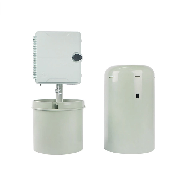
Composition of optical distribution box
It is widely adopted in FTTx cabling for both fiber cabling, provides the connection between fiber optic cables and passive optical splitters. Fiber Distribution box contains the shell, the internals (supporting frame, set fiber disc, fixing device) and optical fiber. The fiber distribution box, a crucial component in optical fiber networks, serves a dual purpose of managing and protecting optical fibers while facilitating their efficient distribution. Whether you're building a central office, data center, or FTTx distribution network, understanding the right ODF. ication and relevant standards over the range of optical wavelengths from 1260nm to 1625nm. However, component desi n should also take account of future requirements to extend operating wavelength to 1675nm. Cross-con-nections and direct connection can be two ways to.
[PDF Version]
-

Armenia Passive Optical Network Low Voltage Circuit
INCRIPT provides project development and management, turnkey solution implementation, installation, commissioning, and technical maintenance of low-voltage systems. The Relevance Inspector will open in the Coveo Administration Console. Our integrated circuits and reference designs help you create optical network terminal (ONT) units that enable high-speed data connections for today's passive optical networks. Use the resources below to design a system with our. INCRIPT emerges as a proficient systems integrator with over a decade of extensive experience in the Armenian market. Since its inception, the company has continuously evolved, refining its expertise in designing, building, and upgrading IT infrastructure and engineering systems. We offer turnkey. This paper presents the design and implementation of a passive optical network (PON) based on a gigabit-capable passive optical network (GPON) standard to deliver fiber-to-the-home (FTTH) services in a small-town setting. 5% of people in rural areas have access to the Internet, but only 73. The construction and deployment.
[PDF Version]