-
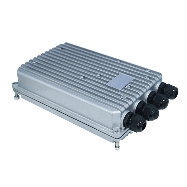
Requirements for Optical Module Circuit Boards
Since they are used to interconnect electronic devices, optical module PCBs are designed to meet several requirements, such as supporting high-speed data transmission, dissipating heat, and enabling hot-swapping. Optical module PCB design demands exceptional accuracy to ensure stable and. This guide serves as an in-depth resource for engineers, designers, and project managers involved in the development of optical module PCBs. 1 mm in thickness, with most designs comprising ≤12 layers. These materials lower energy loss and help high-frequency work better.
-
Increase the light output power of the optical module
An optical amplifier is a device which receives some input signal light and generates an output signal with higher optical power. Typically, inputs and outputs are laser beams (very rarely other types of light beams), either propagating as Gaussian beams in free space or in a fiber. At the receiver end, the optical signals are reconverted into electrical. In this guide, we will explain what optical signal strength is, how to check it on Cisco IOS using the command line, and how to troubleshoot common light level issues. Assume the. This application note gives a short introduction to optical modules and the need of an optimized power tree in them and then concentrates on the use cases and benefits of four-switch and inverting buck-boost converters inside optical modules.
-
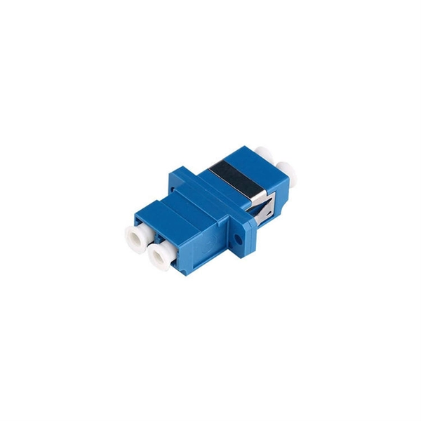
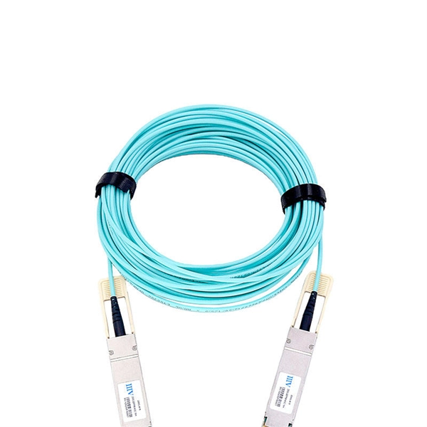
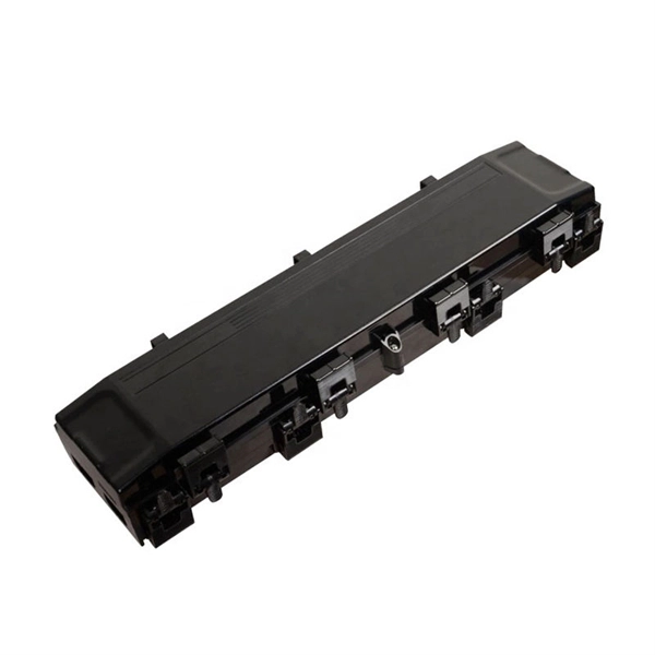
Which interface should be used for the fiber optic drop box to optical module
Most SFP fiber optic modules use LC connectors, while SC connectors are mainly found in legacy networks and MPO/MTP connectors are used for high-density cabling rather than directly on standard SFP modules. This connector landscape reflects how modern SFP deployments prioritize port density and. An optical fiber patch Cable is a jumper wire used to connect from equipment to an optical fiber cabling link, and it is usually used for the connection between an optical transceiver and a terminal box. Fiber optics are used in many applications, including medical imaging, automotive, military, industrial, and commercial (e. A key advantage of SFP+ Modules is that they are "hot-swappable", meaning they can be swapped out while the router is still powered on. They also offer flexibility in cabling options, as you can.
-
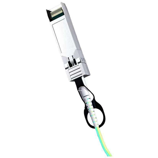
How to enable the optical module after plugging it into the optical port
Align the SFP module with the optical port and insert it horizontally, pressing firmly until the bottom of the module engages with the locking spring of the optical interface. Figure 1 SFP Optical Module Installation. The Cisco Small Business Series Switches allow you to plug in a Small Form-factor Pluggable (SFP) transceiver in their optical modules to connect fiber optic cables. Once the transceiver and fiber optic cable are plugged in properly in the switch optical module, you should be able to view the. This section describes how to install optical transceivers on the SFP or SFP+ ports and connect them to the ports of the peer device using optical fibers according to the network plan. The USG supports both 1 Gbit/s, 10 Gbit/s, and 40 Gbit/s optical modules. The LED will only light up when all connections are properly established and functioning correctly. The installation process can be taken by the following instructions.
[PDF Version]
-
Is the R-port on the optical module for receiving or transmitting light
ROSA is the component inside the receiver side of the SFP port. The ROSA is responsible for receiving the optical signal transmitted by the TOSA of the opposite end's transceiver and converting it back to an electrical signal so that the communication equipment can understand it. Optical modules typically have an electrical interface on the side that connects to the inside of the system and an optical interface on the side that connects to the outside. The integrated optical transceiver module is the core device of optical communication, which completes the optical-electrical/electrical-optical conversion of optical signals. We'll cover everything from physical form factors to spectral characteristics, modulation formats. Ensures a proper connection between the optical module and the optical port of the device. It exists only on an SFP optical module.
[PDF Version]
-
How to view the optical module registers
It is integrated in the Device Control Panel, but may be undocked and moved around the screen independently. The operator can hide and show the Register View by clicking on the Reg. View button or use the F6 shortcut. Register settings can be exported to text files and likewise. If an optical module on an interface is faulty, you can run the display commands to view information about the optical module. Related Information Video Identify a Huawei-Certified Optical Module Run the display transceiver [ interface interface-type interface-number | slot slot-id ] [ verbose ]. The following introduces the specific operations to view the working status and internal information of an optical module on a Cisco switch. The Cisco Small Business Series Switches allow you to plug in a Small Form-factor Pluggable (SFP) transceiver in their optical modules to connect fiber optic cables. 5um) Digital Diagnostic Monitoring :YES Vendor Name.
[PDF Version]
-
How to cut optical cables after production
Cutting fiber optic cable requires precision and the right tools to avoid damaging the delicate glass fibers that transmit data; the correct method involves scoring the outer jacket and then snapping the cable clean, ensuring a clean break for future splicing or termination. In this video, you will learn how to cut optical fiber cable step by step. This tutorial is perfect for beginners and professionals working with fiber optic cable installation and maintenance. You may also want to. 1. 1 Improper use of a respooler (Figure 1) can cause damage to a cable jacket or result in wavy fiber in tight buffered cables due to cable crossovers or excessive tensile loading. These cables are made of extremely The content is structured to help readers understand the key concepts and practical applications.
-
The SFP optical module does not have an FC interface
Small Form-factor Pluggable (SFP) is a compact, hot-pluggable network interface module format used for both telecommunication and data communications applications. An SFP interface on networking hardware is a modular slot for a media-specific transceiver, such as for a fiber-optic cable or a copper cable. The advantage of using SFPs compared to fixed interfaces (e.g. modular connector. SFP typesSFP transceivers are available with a variety of transmitter and receiver specifications, allowing users to select the appropriate transceiver for each link to provide the required optical or electrical reach over. Quad Small Form-factor Pluggable (QSFP) transceivers are available with a variety of transmitter and receiver types, allowing users to select the appropriate transceiver for each link to provide the required optical reach over. SFP sockets are found in, routers, firewalls and. They are used in Fibre Channel and storage equipment. Because of their low cost, low profile, and ability to provide a c.
[PDF Version]
-
What is the maximum speed of the optical module
6T transceiver is an optical module designed to handle data transmission at a speed of 1. These modules, including SFP, SFP+, and SFP28, are widely used in enterprise networks, data centers, and carrier-grade deployments. Lanbras Optical Module and Cable solutions cover up to 800G, 1. Our products ensure low latency, high. As data center speeds increase, the reliability and power efficiency of the SFP optical module become paramount, directly impacting overall system thermal management and uptime. A robust optical backbone is only as strong as the transceivers linking the components. Key characteristics include: Speed: 1 Gbps, 10 Gbps, 25 Gbps, or higher. It uses 8 electrical lanes, each.
-
Normal transmit and receive power of optical module
Transmit power is typically good when it is in the 6 dB range between -1 and -7 dBm. This guide provides average transmit and receive power ranges for transceiver modules. The TX (transmit) and RX (receive) power levels significantly affect everything from signal strength to transmission distances and the overall optical power. For network engineers working with fiber optics (SFP, SFP+, QSFP), understanding TX (Transmit) and RX (Receive) signal strength is critical.
-
Optical module CFP signal
The C form-factor pluggable (CFP, 100G form factor pluggable, where C is : "hundred") is a to produce a common form-factor for the transmission of high-speed digital sign. The CFP transceiver is specified by a (MSA) among competing manufacturers. The CFP was designed after the (SFP) interface, but is significantl.
-
How does the optical module test group perform its tests
Optical modules will go through strict testing and quality inspection procedures before shipment, such as material testing, parameter testing, aging testing, real machine testing, end-face testing, etc. In fiber optic networks, optical transceivers such as SFP, SFP+, QSFP28, and QSFP-DD play a vital role in converting electrical signals into optical signals and vice versa. Testing these modules ensures performance, compatibility, and long-term reliability in bandwidth-intensive environments like. QSFPTEK suppliers have strict transceiver testing and quality control processes, and each optical module is delivered with a complete testing process. Optical modules can realize end-to-end signal transmission, and it performs optical communication through optical fibers. However, due to the architectural differences between 4-channel and.
[PDF Version]