-
Attenuation of the backbone optical cable
Attenuation in fiber optics is the gradual loss of light signal strength as it travels through a fiber cable. This can be due to a variety of factors: scattering and absorption, intrinsic loss, extrinsic loss, bending losses and more. If you don't know what kind of losses to expect in your system, you won't know how many other components. The uses various types of network cables, including multimode and single-mode fiber-optic cable. This section specifies requirements for telecommunications optical fiber backbone cabling. VA Infrastructure Standard for. Optical Signal Attenuation is the single greatest factor limiting the distance and performance of your network. dBm difference: A(dB) = Pin(dBm) − Pout(dBm). Select a mode that matches your task.
-
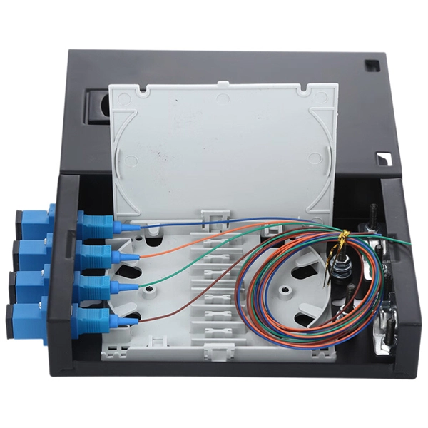
Coupler connection to optical fiber
Fiber optic couplers can either be passive or active devices. Passivefiber optic couplers are said to be passive as no power is required for operation. They are simple fiber optic components that are used to redirect light waves. Passive c. Fiber optic couplers can either be passive or active devices. Passivefiber optic couplers are said to be passive as no power is required for operation. They are simple fiber optic components that are used to redirect light waves. Passive couplers either use micro-lenses, graded-refractive-index (GRIN) rods and beam splitters, optical mixers, or spl. Types of fiber optic couplers include splitters, combiners, X-couplers, trees, and stars, which all include single window, dual window, or wideband transmissions. Fiber optic splitterstake an optical signal and supply two outputs. They can further be described as either Y-couplers or T-couplers. 1. Y-couplershave equal power distribution, meaning t. When specifying optical couplers you should consider the fiber optic cable, the coupler type, signal wavelength, number of inputs and outputs, as well as insertion loss, splitting ratio, and polarization dependent loss (PDL).
[PDF Version]
-
Which is more reliable for high-precision planar optical waveguides in operator backbone networks
Consider the case of the guided mode propagating along an optical waveguide via series of total internal reflections at the core–substrate and core–cladding interfaces, as shown in Fig. 1.4a. The critical ang.
-
Is there a connection between power line carrier machines and optical cables
Thus there is a large distance between the equipment and the tuner, and the connection between the two is made using a coaxial cable Fiber Optical (FO) Cable. The coaxial cable provides shielding so that noise cannot get into the cable and cause interference. Optical attached cable (OPAC) is a type of fibre-optic cable that is installed by being attached to a host conductor along overhead power lines. These cables are installed on poles or towers at the. Communication networks are an integral part of interconnected transmission lines in a power grid, analogous to the spinal cord for control signal and information exchange among substations, data hubs, and load dispatch centers. Carrier current used for Power Line carrier Communication has a frequency range of 80 to 500 kHz. PLCC is mainly for telemetry and telecontrol in modern electrical. OPGW (Optical Ground Wire): This is an all-metal cable that holds a large number of optical fibers inside. What Are the Main Advantages of Aerial Fiber Cable? The main advantages of aerial.
[PDF Version]
-
List of Materials for Outdoor Optical Cable Cabling
Each optical cable is constructed using a precise combination of optical fibers, strength members, buffer tubes, water-blocking elements, armoring, and protective jackets. Here is the extended technical table of all raw materials used in the fiber optic cable industry. Fiber optic cables for outdoor applications are engineered to withstand the more demanding conditions seen outside, from environmental extremes to mechanical forces. These are the outdoor fiber optic cables you see strung along telephone poles (aerial), installed inside an underground duct, or even. Fiber optic cables are designed to provide high-speed, no-signal-loss, and EMI-free communication in telecommunication, powergrid, datacenter, broadband, and industrial applications. As the backbone of modern telecom infrastructure, these cables come in specialized designs to operate reliably despite the challenges of humidity, tension, wind, rodents. This document serves as a guide for outdoor fiber optic cable selection and installation for professionals in the telecommunications industry.
[PDF Version]
-

Is the H3C switch an optical port or an electrical port
H3C S1850V2-X switch series comes with standard Gigabit copper ports and Ten-Gigabit optical ports, making it a good fit for complex network environments and network expansion. H3C FS6300V2-EI series switches are a new generation of high-performance, high-port density, high-security Layer 3 Ethernet switches developed by H3C Technology Co. (hereinafter referred to as H3C) using industry-leading ASIC technology, supporting IPv4/IPV6 Dual-stack management and. A Combo port can operate as either an optical port or an electrical port. Inside the device there is only one forwarding interface. You can specify a Combo port to operate as an electrical port or an. This video provides a comprehensive guide on configuring and troubleshooting Combo ports on H3C Ethernet switches. Reasonable cable routing can improve efficiency by facilitating installation and removal of fan trays, and some other components. Interface cables are routed through the. Packaging Details:1. Rated voltage range: -48 ~ -60V DC.
[PDF Version]
-
10 Gigabit Ethernet card optical module not connected to fiber optic cable
Troubleshooting SFP+ link issues in 10 GbE networks requires attention to module type, match of speed and wavelength, clean fiber connections, correct configuration, thermal management, and equipment compatibility. You can quickly resolve SFP+ Module connectivity issues by following a systematic optical transceivers troubleshooting process. Check for common connection problems, such as link failures or modules not recognized. Check compatibility between the optical module and switch Most switch brands have specific compatibility requirements. During network upgrades, many enterprise users encounter a common issue: after replacing 10G broadband lines or inserting 10G SFP+ optical modules, the switch still fails to operate at full 10G bandwidth or even fails to recognize the modules. We've listed the five most common ones. First of all, let's briefly recap what SFP and SFP+ stand for. SFPs – short for 'small form-factor pluggable' – are compact, hot-pluggable devices.
[PDF Version]
-
The function of optical cable coiling
The coiling system must maintain balanced tension, consistent feed speed, and smooth direction transitions. The modern coiler uses a wire arrangement tool to ensure perfect layering—each loop sits exactly beside the previous one, maintaining the coil's structure. The modern fiber optic cable is the backbone of global communication networks, connecting continents through vast data highways. Today's automatic winding tools have. Fiber optic cable filling compound is not ordinary “grease” or “petroleum jelly,” but rather a semi-transparent paste-like functional material composed of base oils, thickening systems, water-blocking components, antioxidant systems, and other materials. The cable coiling and reserving device has a simple structure, offers convenient assembly and use, and can avoid accidental pull-out of a coiled and stored cable caused by. The CableCoiler 1300 is a standalone, fully synchronized high performance cable coiler for Schleuniger cut and strip machines. Often, coils are made with a.
[PDF Version]
-
How to convert an electrical port to an optical port on a switch
A switch SFP port converts electrical signals into optical signals via SFP transceivers, or maintains them electrically for copper connections. By using an SFP to RJ45 adapter (e. 5G SFP), you can seamlessly connect legacy Ethernet devices to modern fiber-optic. The RJ45 port is a built-in electrical port of a Gigabit Ethernet switch, and it is mainly connected by Category 5, Category 5e, Category 6, and Category 6e twisted-pair cables. However, modern networks often combine both technologies. The good news: you can bridge them easily using the right hardware, such as media. An SFP port on a switch or router SFP port enables network engineers to connect multiple media types, from fiber optic links to copper Ethernet. An SFP transceiver acts as a compact, hot-swappable optical transceiver that.
-
Optical module receiving sensitivity is less than
Receive sensitivity defines the minimum optical power required to maintain an acceptable bit error rate (BER ≤ 1E-12) at specific data rates. It's a core parameter in optical transceiver specifications, indicating the module's capability to detect weak incoming signals. What Is BER? The bit error rate (BER) measures the data transmission precision within. In optical communication systems, sensitivity is a measure of how weak an input signal can get before the bit-error ratio (BER) exceeds some specified number. For example, SONET specifies that the BER must be 10 -10 or better. This level must fall within the receiver's power range.