-
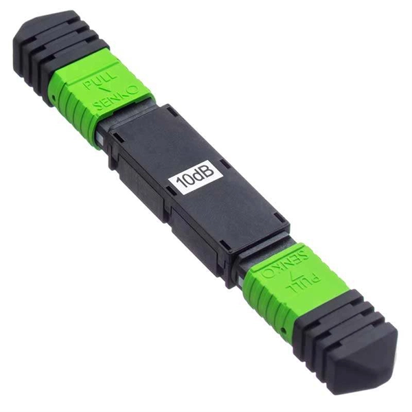
How much optical loss does a fiber optic cold connector typically experience
Generally, for single-mode connectors, the recommended insertion loss is below 0. Insertion loss, also known as attenuation, is the loss of optical power that occurs when light passes through a fiber optic connector. It is caused by factors such as misalignment, air gaps, and imperfections in the connector components. This article explores various connector types—such as SC, LC, FC, ST, APC, and UPC—and analyzes how their design and polishing affect IL and RL performance. Insertion Loss (IL): Measures the. Fiber loss, also called fiber optic attenuation or attenuation loss, refers to the loss of signal between input and output.
-
Causes of phase loss in relay protection
Typically, a phase loss is caused by a blown fuse, thermal overload, broken wire, worn contact or mechanical failure. Phase loss protection refers to safeguarding the power system when a phase is lost in a three-phase AC supply. It not only drives large motors but is also widely used. A phase failure (or) phase loss happens when the voltage in one (or) more of electrical phases reaches (or) approaches zero. Conductor failure, insulation failure, equipment (contactor, overcurrent device, transformer, etc. ) failure often related to aging, and improper. Three-phase electrical systems are the backbone of industrial and commercial power distribution, prized for their efficiency and reliability. Knowing why it happens helps you avoid expensive fixes.
-
Splitter Optical Path Loss
5 dB depending on splitter type. Optional: patch panels, attenuators, or extra components. Helps cover dirt, aging, and measurement tolerances. Calculate insertion loss for passive optical splitters in PON and distribution networks. Excess loss accounts for manufacturing imperfections, typically 0. DISCLAIMER: These calculators are provided for. Optical splitters play a crucial role in Fiber to the Home (FTTH) Passive Optical Network (PON) systems, efficiently distributing a single optical signal to multiple destinations. Common values: 2, 4, 8, 16, 32, 64. Understanding the types of splitters, their impact on network performance, and how to measure their losses ensures high-quality network operation and facilitates optimal splitter selection based on. Understanding optical splitter loss isn't just about plugging numbers into a calculator.
[PDF Version]
-
How much splitter loss is used to calculate optical power
Insertion loss tells you how much weaker the signal becomes after passing through the splitter. Let's say you have a laser output at 0 dBm (which is 1 milliwatt of optical power). Factors influencing splitter loss include splitter. Instantly compute insertion loss, power at each subscriber port, and fade margin for PLC and FBT splitters — including dual cascade configurations. Covers GPON (1490 nm / 1310 nm), EPON, and RF video overlay (1550 nm). Add connector and splice quantities with realistic planning losses. Enable power budget to estimate received power and margin. Splitters are essential when you want one fiber line from a central office (like an ISP's headend or data center) to serve multiple homes or businesses.
-
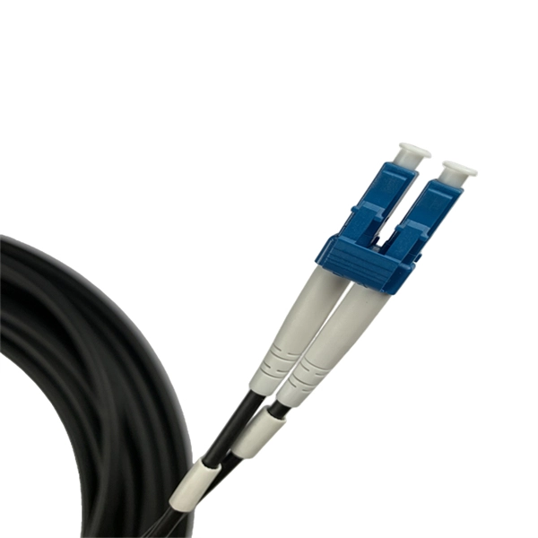
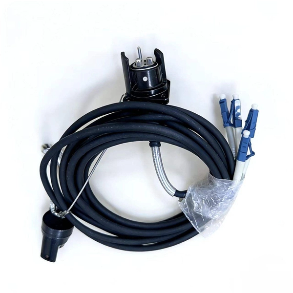
How to choose a connector for tightly wrapped optical cable
This guide covers the most common fiber connectors, including LC, SC, ST, FC, MPO/MTP, and specialized industrial connectors. You'll learn about their design, applications, performance parameters, and industry standards to help you make informed decisions for your fiber. Fiber optic cable assembly quality hinges on selecting the right connector type—most commonly LC, SC, or ST—to match device ports and installation environment. LC connectors dominate high-density panels and modern transceivers (SFP/SFP+, QSFP), while SC remains common in enterprise and FTTH; ST. From fiber optic cable connectors used in data centers to optical fiber termination types for harsh industrial environments, understanding the differences and applications of various connectors is essential. Knowing what each connector does is essential, but it's also important to match them with the right equipment, fiber type, and performance needs. 5 µm wide, the alignment tolerance for any type of fiber.
[PDF Version]
-
451 Standard Optical Cable Connector
Versatile as well as space-saving for ribbon cable applications, 3M™ Ribbon Cable Wiremount Socket 1. 050") Pitch 451 Series is a robust connector in a small package. It features a socket body in multiple positions, along with a cover and an optional strain relief. These compact, robust connectors with a fine pitch enable high. The 451 series socket assemblies and 452 series board-mount headers from 3M feature small packages for minimizing the PCB space and 30 µAu and Au flash plating versions for multiple mate and unmate cycle option levels at different price points. 025" PITCH MPATIBILITY: 3M. 050"), SERIES 452 HEADER WITH L HE EVENT OF CONFLICT BETWEEN THIS DATA AND THAT CONTAINED IN RE CE RELATED DOCUMENTS: PRODUCT SPECIFICATION: 3 DOC.
-
Loss value of new optical cable 1310
Used to suggest a default attenuation value. Route length between active equipment. Usually higher loss than fusion splices. Include patch. At Aeliya Marine Tech, we strive to provide efficient and reliable shipping services to our customers worldwide. Please read the following information regarding our shipping policy: We offer various shipping options for each country, and the methods and costs are clearly indicated on all. Calculate link or channel loss and determine the supported applications and max lengths for the configuration. You can also select components to configure connections below. QuestTel shall have no liability for any error or damage of any kind resulting from the use of this document. Connector and Splice Losses: Every connector or splice in a fiber optic network introduces additional. This document outlines the specifications for a single-mode optical fiber and cable designed for use around the 1310 nm zero-dispersion wavelength, suitable for both the 1310 nm and 1550 nm regions, and compatible with analogue and digital transmission. It details the fiber's geometrical, optical.
[PDF Version]
-
How to check optical loss on a Huijue switch
Execute the command, display transceiver [ interface interface-type interface-number | slot-id ] [ verbose ] to check the optical module information on the device interface. During use, reading optical module information helps understand its real-time operating status, enabling faster troubleshooting of link abnormalities. The following uses the. Here is an example on how to query or display optical power of an interface in a Huawei Router. from transceivers Check “Alarm information” section for warnings, LOS Alarm means no inbound signal, execute display this to check shutdown mode, execute undo shutdown if necessary. Execute the command, display.
-
Bolivia s tariff cost for transparent optical fiber cable G 652
Free Bolivia tariff calculator and customs duty calculator. Bolivia calculates using the CIF method, which means the import duty and taxes are calculated based on the value of the imported goods as well as shipping costs. It details the fiber's geometrical, optical. CRU provides comprehensive, accurate and up-to-date price assessments and research reports for bare optical fibre across various key regional markets, combined with insights into the factors and events affecting markets.
-
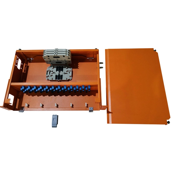
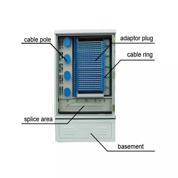
How to waterproof the connecting pipe of the optical distribution box
The cap-type splice box uses a heat-shrinkable sleeve to seal the lead-in part of the optical cable into the splice box, and connects the line optical cable and the splice box as a whole. The upper and lower covers squeeze the rubber ring to make it waterproof. Extended size. Waterproofing an electrical connection is all about creating a bulletproof barrier against moisture.