-
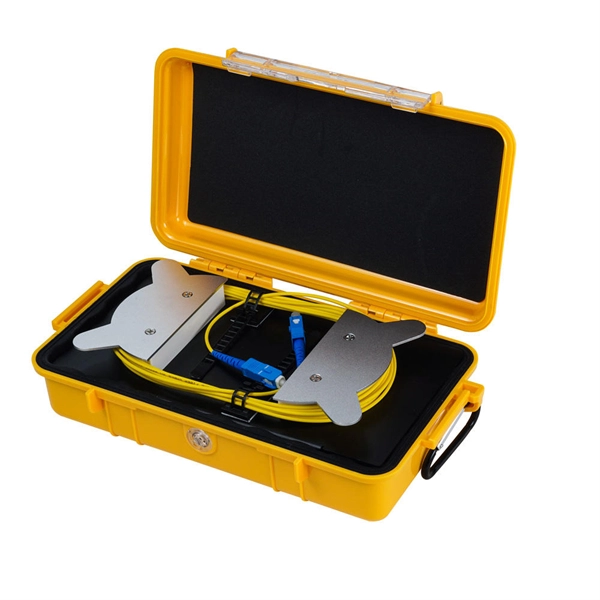
The Function of Protective Housing for Fiber Optic Sensors
Rugged casings (reinforced polymer) are made with high-quality plastics, silicone, or rubber, and have reinforced corners to protect a device from impact. For sensors, it will help absorb shock and prevent cracking. The purpose of this study was to compare the effectiveness of polyimide and nitinol protective housing designs to anchor pressure sensors to muscle tissue, prevent IMP measurement artifacts, and optimize the force-IMP correlation. Anchoring capacity was quantified as force required to dislodge. They record physical variables such as temperature, pressure, humidity or movement and translate these into electrical signals that can be processed by other systems. In smartphones. An IP rating of IP67 represents a level 6 for dust protection. Stainless steel is the perfect choice for sensor housing, especially in harsh environments. For example, the Atlas Scientific EZO Embedded Humidity Probe is weather resistant.
[PDF Version]
-
The Development History of Fiber Optic Acoustic Sensors
Fiber-optic interferometric acoustic sensors were first proposed for US Navy applications 36 years ago. This paper will review the origin, development and deployment of these sensors. Future applications will also be discussed. This content is available for download via your institution's subscription. To access this item, please sign. Fiber‐optic sensor technology has experienced tremendous growth since its early beginnings in the 1970s with early laboratory demonstrations of fiber‐optic gyros and acoustic sensors and the introduction of the first commercial intensity and spectrally based sensors. These early efforts were. The Design Of Fiber Optic Sensors For Measuring Hydrodynamic. Navy's effort to develop sensors that used optical fiber to detect targets at sea offers a window into how a technology goes from basic research to production.
[PDF Version]
-
How to measure wear using fiber optic sensors
When the wafer dicing saw processes hard and brittle materials, the wear rate of the grinding wheel blade accelerates. To detect blade wear in time, a grinding wheel blade wear detection method based on a f.
-
How many fiber optic sensors are there
Based on the sensing method and the placement of the fiber emitter and receiver, there are three types of fiber optic sensors: through-beam, reflective, and retro-reflective. Fibers have many uses in remote sensing. Depending on the. Fiber optic sensors can be divided into point sensors and distributed sensors according to their working principles.
-
What signals can fiber optic sensors detect
Unlike traditional electrical sensors (e., proximity switches or pressure sensors), it operates not by electrical signals but by detecting changes in light—such as intensity, wavelength, or polarization direction—to measure an object's position, distance, temperature, or even. Unlike traditional electrical sensors (e. The basic working principle is that when the light signal passes through the optical fiber, parameters such as light intensity, wavelength, and phase will be affected by the. Fiber optic current sensors are revolutionizing the way electrical currents are measured, providing high sensitivity, immunity to electromagnetic interference (EMI), and the ability to function in harsh environments. The fiber optic sensor has an optical fiber connected to a light source to allow for detection in tight spaces or where a small profile is beneficial. Depending on the. A sensor is a device that measures a physical quantity and converts it into a signal.
[PDF Version]
-
Extinction Ratio of Fiber Optic Sensors
In the world of fiber optics, the extinction ratio is a critical yet often overlooked parameter that can make or break signal integrity. This article explains what extinction ratio is, why it matters for reducing bit error rates in optical communication, and how it impacts optical module. Comprehensive Guide to Polarization Extinction Ratio in Fiber Optic Sensor s Introduction to Polarization Extinction Ratio The polarization extinction ratio (PER) is a critical parameter in fiber optic sensors that measures the degree of polarization extinction between two orthogonal polarization. Extinction ratio measurement at the connector level can quickly reveal alignment issues. The polarization axes of both fibers must be aligned before fusion. A poorly aligned splice is one of the most common sources of PER loss in. Cross coupling in regards to a birefringent fiber, quantified by extinction ratio, indicates the amount of light which is able to mix between the two polarization axes. To overcome this limitation, we propose and demonstrate a novel resonator design with an intrinsically high polarization.
[PDF Version]