-
DC busbar power failure
If the busbar protection fails to trip when an external fault occurs or if it falsely trips while in use, the power system could become unstable. A total power outage will result from this. Regular dielectric testing is crucial to verify the quality of insulation and ensure that busbars can perform reliably under both normal. Busbar insulators are the backbone of electrical systems, ensuring safe power distribution by isolating conductors and preventing faults. However, harsh operating conditions, material degradation, and improper maintenance can lead to insulator failures—jeopardizing safety and system reliability. The DC-link capacitor selection is one of the first and most important steps. Consequently, power busing design needs critical consideration in terms of performance under converter operation, asymmetric loading, short-circuits, thermal and insulation breakdown.
[PDF Version]
-
Nordic Cable Tray and Busbar Manufacturer
We know cable management systems. Hilding Group consists of the three companies Nordic Wire Tray, Hiltec and Hilcon. Cable trays has an overall mission: to organize cables. In order to successfully meet the market's demands, high requirements and adaptations to various industries, a broad and well-thought-out range is required. Nordic Wire Tray's cable laying system consists of wire trays sold under the X-Tray. We specialize in manufacturing high-quality cable support systems. Our product range includes galvanized steel and acid-proof steel cable ladders, cable trays, wire mesh trays, lighting tracks, and aluminum-frame cable management systems, socket poles, and the unipro® lighting track system. Material Hybridization: Combinations of powder-coated metal, stainless steel, and solid wood or MDF are prevalent. New name, new look, same Nordic quality We continue to drive innovation in cable. Our cable management systems are designed to withstand the toughest conditions in C5-M environments, while delivering cost-effective and flexible solutions for platforms, vessels, and ports.
[PDF Version]
-
Mns switchgear busbar compartment height dimensions
Independent main busbar compartment is on the top part which is separated from the device compartment. In no event shall ABB be liable for direct, indirect, special, incidental, or consequential damages of any nature or kind arising from the use of this document, nor shall ABB be liable for incidental or consequential damages arising from use of any software. The MNS R frame is based on modular 2 mm thick still C sec-tions, pre-drilled at a pitch of 25 mm. The switchgear is pre set for easy extensions on both sides. The ends are designed to allow installation of future sections. With a rated voltage of up to 1000 V AC or 1500 V DC and a rated current of up to 6300 A, it offers exceptional performance and reliability. This together with the global service and support network established in over 30 manufacturing locations world wide ensures that the choice of MNS® will be the EC 61439 -1/2.
[PDF Version]
-
High-pressure pipeline of busbar
The busbar pipe is perfect for electrical systems requiring reliable high-pressure insulation and continuous busbar pathways. llel cables, rigid bus bar system or flexible bus bar systems. This article delves into the concept of injection molded busbars, their advantages, manufacturing. This Tech Bulletin provides an overview of how new complex multi-layer molded busbar technologies can deliver significantly improved electrical performance from batteries to the power inverters and into the motors, while at the same time streamlining overall assembly processes. Typically, they are a strip, a bar or sometimes a tube made of copper, brass or aluminum optimized for.
-
Protection level of busbar connectors
The International Electrotechnical Commission (IEC) sets out standardized testing procedures and benchmarks to ensure that busbar contact resistance remains within safe and acceptable limits. IEC standards are developed through international consensus and are used globally. The integrity of busbar joints is critical because. Busbars in power systems are the location where transmission lines, generation sources, and distribution loads converge. Because of this convergence, short circuits located on or near the busbar tend to have very high magnitude currents. The high magnitude fault currents require high-speed. Industry data shows that loose or improperly torqued busbar connections account for a significant percentage of electrical panel failures. Busbar distribution ensures these requirements are fully met. Performance criteria of. DEFINITIONS.
[PDF Version]
-
The function of the small busbar in the switch cabinet
A busbar is a metal bar, usually made of copper or aluminum, that carries electricity inside switchgear. It connects the incoming power to circuit breakers and outgoing circuits, helping power flow smoothly and evenly. Good busbar design helps prevent overheating and electrical. Busbars are the backbone of a low-voltage switchboard: rigid conductors that collect and distribute current safely between incoming devices and outgoing feeders. It connects. The use of busbar systems with their versatile rail-adaptable connection, switching and installation devices is an ideal and cost-effective electrotechnical enhancement of modern distribution boards thanks to their small footprint, modular design and quick assembly contacts. Small Busbar Room (Top of the Cabinet): Houses busbars that distribute electrical power to different sections.
[PDF Version]
-
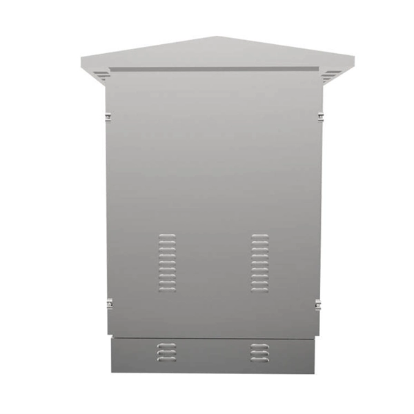
El Salvador Broadcast Transmission Busbar Wall-Mounted
Electrical busbar systems (sometimes simply referred to as busbar systems) are a modular approach to, where instead of a standard cable wiring to every single electrical device, the electrical devices are mounted onto an adapter which is directly fitted to a current carrying. This modular approach is used in, panels and other kinds of installation in an electrical enclosure.
-

Connect the copper busbar in the computer room to the ground wire of the distribution box
Grounding electrode conductor (GEC) – wire connecting the panel to the ground rod. Drive a ground rod into the earth near the panel. This position is the connection point of the grounding wire in the. The Mesh-BN is the backbone of the bonding system, designed to ensure a uniform electrical potential across the entire data center. Now, let's. An electrical ground bus bar is a conductive bar made from materials like copper or aluminum, and it serves as the central point for connecting multiple grounding conductors in an electrical system. Grounding is one of the most crucial safety measures in electrical installations, and the bus bar. AI workloads, GPU clusters, and high-performance computing are pushing server rack power density to new extremes — from the historical 5-7 kW per rack to 20-40 kW or more. Our kits are available as one kit per rack to allow for ease of stocking and reordering.
[PDF Version]
-
Does the high-voltage switchgear have a busbar
Busbar can be made of materials such as copper or aluminium and are typically found in medium-voltage and high-voltage switchgear. The distribution of electrical power through a busbar is done through a process called busbar tapping. You must strictly follow these. Busbar design in switchgear ensures safe, reliable power distribution by balancing current capacity, thermal performance, mechanical strength, insulation, and standards compliance. They are also used to connect high voltage equipment at. The starting point for planning a switchgear installation is its single line diagram. You'll find it in power plants, substations.
-
How to ground the busbar of the switchgear
Bus bar grounding can be achieved by one of two methods: grounding clamps applied to bus bars or a separate switchgear section with a switching mechanism dedicated to ground. In most assemblies you will find horizontal main bars, vertical risers, neutral and equipment-ground buses, and purpose-designed. The purpose of this manual is to assist the user in developing safe and eficient procedures for the installation, maintenance and operation of the equipment. For additional information, refer to NEMA Standards Publication PB2. Dive in to power up your knowledge! These guidelines govern the busbar processing and installation procedures. With the exception of SF6-to-air bushings terminals, all active portions of gas-insulated switchgear (GIS) are contained within grounded enclosures, which means that they are not susceptible to inadvertent contact. This makes gas-insulated switchgear intrinsically safe. In addition, numerous. New Approaches for Maintenance Grounding in Medium-Voltage Switchgear by Joe Richard and David Mabius Executive summary Maintenance grounding has traditionally been performed by maintenance personnel working in close proximity to open switchgear.
[PDF Version]
-
Switch cabinet busbar installation
In North America, follow UL 891 construction and NEC Article 408 installation practices: use listed/approved hardware, lugs, or tap-off provisions intended for the bus. The matrix below helps engineers finalize material, arrangement, plating/insulation, and verification. The GRL busbar system makes distribution cabinet installation fast, flexible, and neat. At this stage, the supports have been installed in accordance with the installation plan. Ever wondered how busbars, the unsung heroes of electrical distribution, are processed and installed? This article delves into the intricate steps of busbar selection, preparation, and installation, ensuring efficient and safe power distribution. The application of these rules means strict compliance, not only with applicable regulations and standards, but also with manufacturers'. Bus bars play a crucial role in electrical distribution systems by providing a reliable and efficient way to conduct electricity within electrical panels.
[PDF Version]
-
Small busbar acceptance standards and procedures
This article details the comprehensive standards for installing and inspecting busbars, including support brackets, insulators, and bus duct systems. You'll learn essential guidelines and. For complete safety instructions and precautions, always refer to the test equipment instruction manual. This approach is applicable to all types of metal enclosed busbar. Check for physical damage/defects. Check the bus arrangement to ensure that it is consistent with the approved plans. Compliance with recognized quality standards ensures electrical safety, reliability, and regulatory acceptance, especially for telecom, data centers, and industrial electrical applications. Buyers often. IEC 61439 is a standard developed by the International Electrotechnical Commission (IEC) that covers design verification for low-voltage electrical products and assemblies. Main keywords for this article are Bus Bars and Bus Ducts Design Requirements, ANSI C37.
[PDF Version]