-
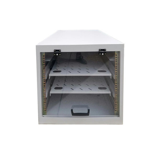
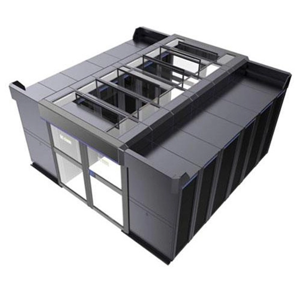
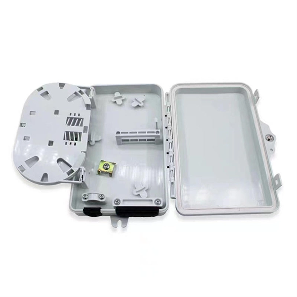
Manufacturer of Single Fiber Optic Distribution Cabinets
Get custom solutions: Our trained and skilled engineering team can create variations of our fiber optic cabinets based on the size, scale and scope of the enclosure that you need.
-
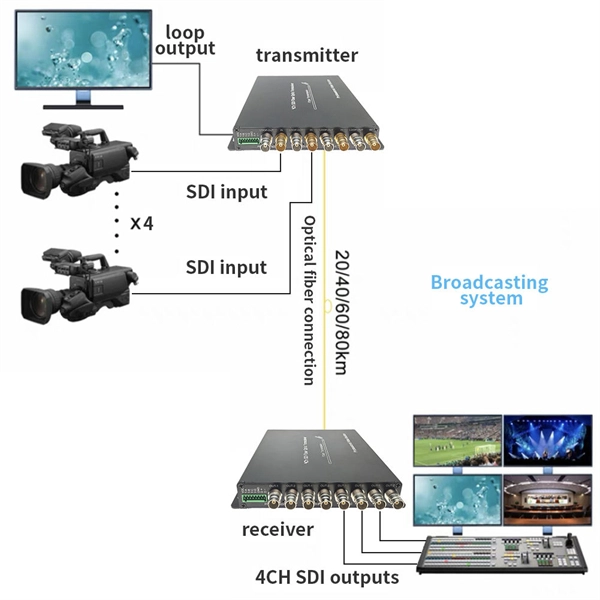
A single optical fiber uses a dual-core optical module
o In optical modules, "core" refers to the light-transmitting channel in the fiber. A 1-core module uses a single fiber core for data transmission, while a 2-core module uses two cores. They are easier to set up and give steady communication. A. Single fiber module also called BiDi transceiver or WDM module. BIDI module only has 1 port, wave filtering through the filter of module, and finished the transmitting of 1310nm optical signal. In today's communication field, single-core optical fibre and dual-core optical fibre are like remarkable stars, the powerful technology behind them and the disruptive impact on the communication industry deserve everyone's attention and discussion.
-
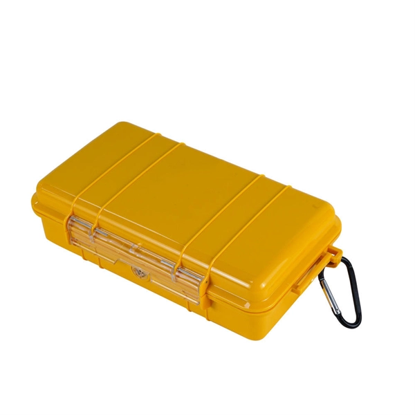
The Function of Protective Housing for Fiber Optic Sensors
Rugged casings (reinforced polymer) are made with high-quality plastics, silicone, or rubber, and have reinforced corners to protect a device from impact. For sensors, it will help absorb shock and prevent cracking. The purpose of this study was to compare the effectiveness of polyimide and nitinol protective housing designs to anchor pressure sensors to muscle tissue, prevent IMP measurement artifacts, and optimize the force-IMP correlation. Anchoring capacity was quantified as force required to dislodge. They record physical variables such as temperature, pressure, humidity or movement and translate these into electrical signals that can be processed by other systems. In smartphones. An IP rating of IP67 represents a level 6 for dust protection. Stainless steel is the perfect choice for sensor housing, especially in harsh environments. For example, the Atlas Scientific EZO Embedded Humidity Probe is weather resistant.
[PDF Version]
-
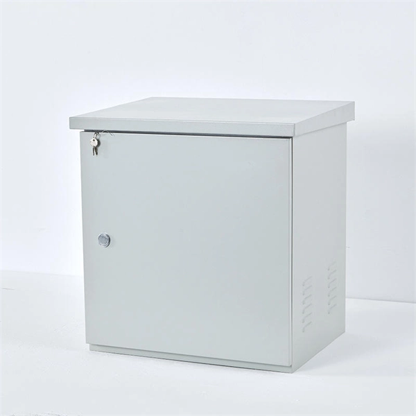
How to deal with abnormal noises from fiber optic terminal boxes
From SPL meters to spectrum analyzers, technology provides the means to uncover these invisible nuisances. Once identified, simple yet effective measures like relocation, soundproofing, and firmware updates can mitigate their impact. A fiber termination box is the standard instrument used in fiber optic networks to connect, secure, and protect optical fibers at the terminating point. When issues like signal loss, slow speeds, or intermittent connectivity arise, systematic troubleshooting is key. Before. Proper troubleshooting can help quickly identify and resolve issues to minimize downtime.
-
Fiber optic cable outer sheath representation
1 The outer cable jacket shall be marked with the manufacturer's name, date of manufacture, fiber count, fiber type, flame rating, listing symbol, and sequential length markings every two feet (e., “CORNING OPTICAL COMMUNICATIONS OPTICAL CABLE - MM/YY. XXXXX (feet. One important consideration when selecting indoor fiber optic cables is the outer sheath material and its fire prevention level. Each cable is single packed in a polybag with a test report that guarantees best performance in typical application scenarios like telecommunication, rack cabling, sensor technologies or indust Choosing the appropriate outer sheath material for fiber optic cables is crucial for ensuring the cable's durability, protection, and performance under specific environmental conditions. At the same time, it must have. 1. 1 The cable shall meet all requirements stated in this specification. Glass fiber and plastic fiber is fragile.
[PDF Version]
-
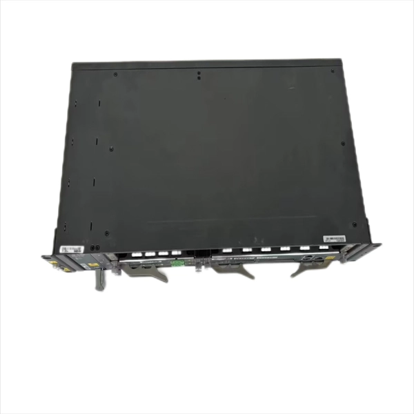
Fiber Optic Single-Mode and Multimode Parameters
Single mode and multimode fiber optic cables are two different types of fiber optic cable aimed at different use cases. Single mode cables are typically made with a single strand of glass at their core, leading to a n.
-
Single-mode port connected to multimode fiber optic cable
Single mode and multimode fiber cables are quite different when it comes to size, light source, signal, and so on. So, they definitely are not interchangeable, and compatibility issues can occur when you try to connect a single mode fiber optic connector to a multimode network. This is where fiber conversion comes in. Single-mode. To realize the short-range direct connection to the end B switch with the same port, the same 10GBASE-SR SFP+ module should be plugged into the end B switch port. What if end B is located in. It's possible because Multi-mode optical cables have a very wide fiber core – 62. Understanding the key differences between these two technologies is essential for IT professionals, business owners, and even homeowners looking to future-proof their network.
-
Fiber Optic Construction Surveying Tools
Design and manage all OSP equipment from cables and conduits, to patch panels and field splitters with this fiber optic management software.Create fiber cable models using the TIA-598C color code specification, create a sub-class of OSP components with custom map icons, design custom line styles and customize data by creating new data fields.View and trace the path a cable strand takes from end to end on the map while viewing all the splice points and fiber termination points.cvFiber has simplified graphical splicing between multiple fiber cables. Users can splice buffer tube to buffer tube and strand to strand, and as well as butt splice two cables.cvFiber is seamlessly integrated with the CircuitVision cvTicket ticketing system that offers outage reporting, ticketing and bulk customer notifications.
-
How to connect a fiber optic cold connector 6
This blog provides a step-by-step guide on how to connect fiber optic cable to connector using a fast cold connector. It explains the installation process, key features, benefits, and common issues. In this article, we will. ⚡ Level Up Your Fiber Skills – Join the One Up Techs Skool 👉 https://www. Please like, Subscribe, and comment any questions you may have. This comprehensive guide covers SC/APC vs SC/UPC fast connectors, selection criteria, installation best practices, compatibility considerations, and application-specific. Proper connection of fiber optic cables is essential to harness these benefits fully, as even minor errors can lead to significant performance issues like signal loss.
-
Can fiber optic cables be run alongside 35kV power cables
General Consideration: It is generally not recommended to run fiber optic cables in the same conduit as electrical power cables. This is due to several potential risks and complications that can arise from such an arrangement. When a communications cable runs parallel and in close proximity to a power cable, these magnetic fields induce unwanted currents—a phenomenon known as inductive coupling—into the sensitive data conductors. This induced noise can. TECHNICAL GUIDELINE July 30, 2020 TG030 Rev. Electrical Interference: Electrical cables can produce electromagnetic. Maintaining proper separation between power, data, and limited energy cabling is foundational to system performance, safety, and code compliance. Other than that you haven't provided much information, given. Laying network cables parallel to electrical cables is often necessary due to space constraints but comes with its own set of challenges, primarily due to electromagnetic interference (EMI).
[PDF Version]