-
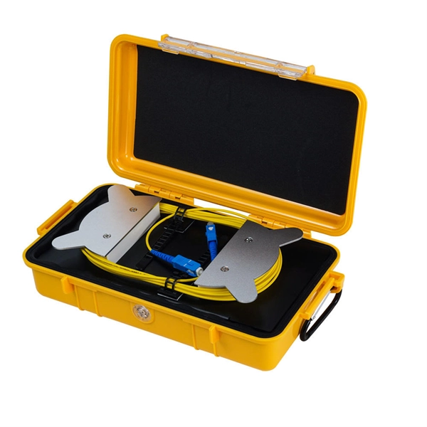
Method for bundling optical cables
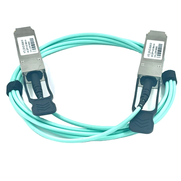
Fiber optic splicing is often the preferred way to connect two fiber optic cables because it has lower light loss (attenuation) and back reflection than connectorization. Fusion splicing and mechanical splicing are the two most common methods of fiber optic splicing. AOCsarrive. This document describes the specifications for preparing, routing, and bundling cables and attaching labels to these cables. Another method of connecting optical fibers is termination or connectorization, which consists of processing the end of a fiber optic bundle so that it can be connected to other fibers or devices through fiber optic. In the rapidly evolving fields of telecommunications, medical imaging, and industrial sensing, fiber optic bundles serve as the cornerstone for efficient and reliable data transmission.
-
Cable Tray Internal Wiring Method
NEC Article 392 explains cable trays, their components, appropriate wiring methods for cable trays, and instances where they are and are not permitted for use. It also focuses on construction and installation practices for cable trays. Here is the summary of the main points found. Hubbell Wiring Device-Kellems and Hubbell Premise Wiring are divisions of Hubbell Incorporated, a U. headquartered manufacturer with over 130 years of supplying solutions for the electrical and data markets. The Cable Tray ng standards, performance standards, test standards and application in this document have been tested extens ompetent professional en completely installed, without damage either to conductors or. The B-Line series Cable Tray Manual was produced by our technical staff. Cable trays give cables a clear path.
-
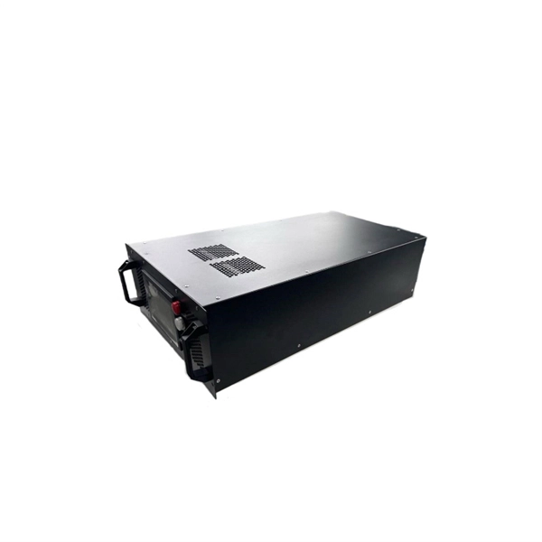
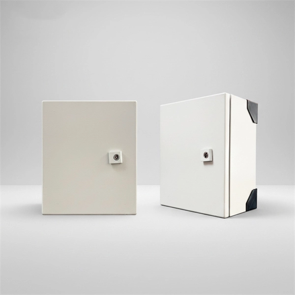
Distribution Box Protection Method
Its primary purpose is to ensure safe and efficient power distribution while providing protection via fuses or circuit breakers against overloads and short circuits. Distribution boxes are built with durable materials, typically metal or high-grade plastic, designed to endure. EPRI has been exploring protective device configuration approaches tar-geted at minimizing the chances of adverse interactions with the power system and the environment. More specifically, electrical faults caused by vegetation, animals, conductor slap, lightning and equipment failures can each. A distribution box, also known as a power distribution box or electrical distribution box, is used to distribute electrical power safely to multiple circuits. Circuit Breakers or Fuses: These safety devices automatically stop the flow of electricity during faults or overloads. Fuses melt when too much current. Electrical systems power our homes, offices, and industrial facilities, but behind every reliable electrical setup lies a crucial component that often goes unnoticed: the distribution box.
[PDF Version]
-
Wiring method for flat iron distribution box
Take the appropriate rating of MCB and RCCB as per your load requirements. Connect the phase and neutral wires from the input power supply to the input of the Main MCB. Connect the output of the Main MCB to the input of the. Learn how to wire a distribution box step by step! This video shows real on-site footage of electrical installation, demonstrating safe and standardized wiring methods used by professionals. Distribution Box Installation: Put the distribution box on the. Material preparation: Prepare the required circuit breakers, wires, wiring ties and other materials, and ensure that they meet the design drawings and installation requirements. Straight lengths are shipped without exterior crating.
-
Installation Method of Cable Trays for Substations
Cable trays provide a strong mechanical support system while maintaining accessibility for inspection, maintenance, and future expansion. This article records the installation process of cable trays carried out in the substation, highlighting procedures, materials . This guide breaks down the whole process for the 35KV substation cable tray construction. We will focus on clarity, simple steps, and, most importantly, safety. My goal is to give you a simple, effective set of instructions. This ensures your 35KV substation cable tray construction meets all the. The installation of cable trays in substations plays a vital role in ensuring organized, safe, and efficient routing of power and control cables. This article. association representing the major electrical equipment manufac-turers in the U. The Cable Tray ng standards, performance standards, test standards and application in this document have been tested extens ompetent professional en completely installed, without damage either to conductors or. MP Husky Cable Trays are NEMA VE 2-2013 compliant. NEMA VE2 was developed by the NEMA Cable Tray Section, of which MP Husky is a charter member.
[PDF Version]
-
Display method of optical power meter
On the display unit, the measured optical power and set wavelength is displayed. Power meters are calibrated using a traceable calibration standard. A traditional optical power meter responds to a broad spectrum of light, however, the calibration is wavelength dependent.OverviewAn optical power meter (OPM) is a device used to measure the power in an signal. The term usually refers to a device for testing average power in systems. Other general purpose light power measuring. The major types are (Si), (Ge) and (InGaAs). Additionally, these may be used with attenuating elements for high optical power testing, or wavelengt. A typical OPM is linear from about 0 dBm (1 milli Watt) to about -50 dBm (10 nano Watt), although the display range may be larger. Above 0 dBm is considered "high power", and specially adapted units may measure u.
[PDF Version]
-
Fiber optic cable lines according to laying method
The routes for laying fiber optic cables may involve ducts, subterranean channels or elevated paths. Installation typically employs two techniques: pulling and blowing. The Fiber Optic Association, Inc. (FOA) was founded in 1995 to help develop the workforce to build the fiber optic networks to support a rapid expansion in communications and the Internet. The charter of the FOA was to promote professionalism in fiber optics through education, certification, and. Below is given the fiber optic cable installation method statement for performing the installation of optical fiber cabling system for any kind and size of project. It forms a critical backbone for modern communication networks across both urban and rural environments.
-
Optical Cable Positioning and Injection Method Operation
In fiber optic cable blowing, high-speed airflow is combined with a mechanical pushing force to produce the installation, known as blowing or jetting. This is the preferred method for pushing fiber optic cable thr.
-
Cable tray horizontal tee cutting method
Completely adaptable, B-Line Flextray is designed to accommodate jobsite changes. For the best results, use a WB30BC Angular Blade Offset Bolt Cutter . to produce a clean cut. Do not use center cut style cutters, as they will leave a rough, burred cut that can damage cables and/o oximately a 45° angle. Cut the bottom wires firs in the order as shown. Flip the tray. To properly bond Hubbell ® painted cable tray, remove the plastic masking device from the trays on each end (exposing the pre-galvanized wire), and splice sections together using Hubbell ® splice kits. For cable trays that are not UL Classified as being “Suitable as an Equipment Grounding. Horizontal Tees link three 10" straight channel sections or compatible transitional fittings, enabling the creation of a sleek and efficient horizontal branch within a fiber routing system. Item code: HT Reducing Tee: W1>W2. Only two splices are required to securely connect tray widths of wire basket tray. The. Use this guide to learn the most effective installation practices when installing Cablofil tray. Engineers and contractors in North America and around the world have found.
[PDF Version]
-
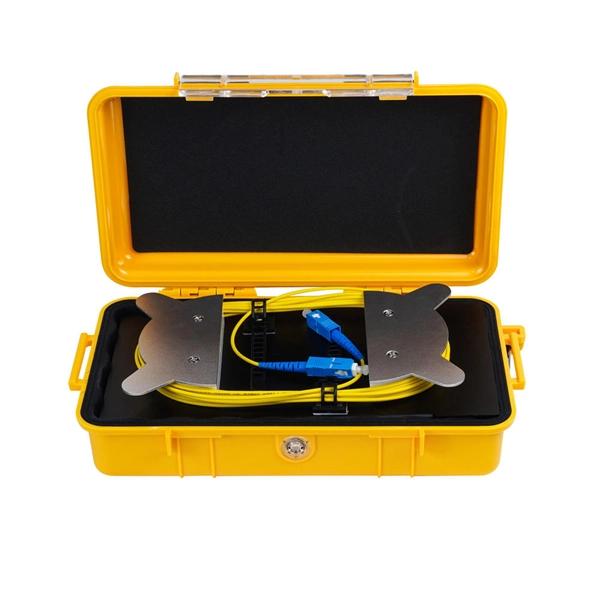
Method for laying 6-core armored optical cable
This guide provides a complete installation process for armored fiber optic cords, explaining each step from routing and pulling to stripping, cleaning, and testing. It also highlights key differences from standard fiber cables and important precautions to ensure safety and performance. The charter of the FOA was to promote professionalism in fiber optics through education, certification, and. Below is given the fiber optic cable installation method statement for performing the installation of optical fiber cabling system for any kind and size of project. The method covers the steps from receiving the materials on the installation site and cable pulling as per the approved shop drawings. Most systems use passive optical network (PON) architectures with signals going through splitters that allow up to 32 users to share one link and carry bidirectional signals. During installation, all curvatures should be smooth.
[PDF Version]
-
Correct Method for Testing Optical Power Meter Readings
Use an optical power meter for this task. You use it to measure the strength of light signals in fiber optic cables. The basic process is straightforward: turn the meter on, set it to the correct wavelength, clean your connectors, plug in, and read the. FOA "Quickstart Guides" are short, simple guides to basic fiber optic tests.
-
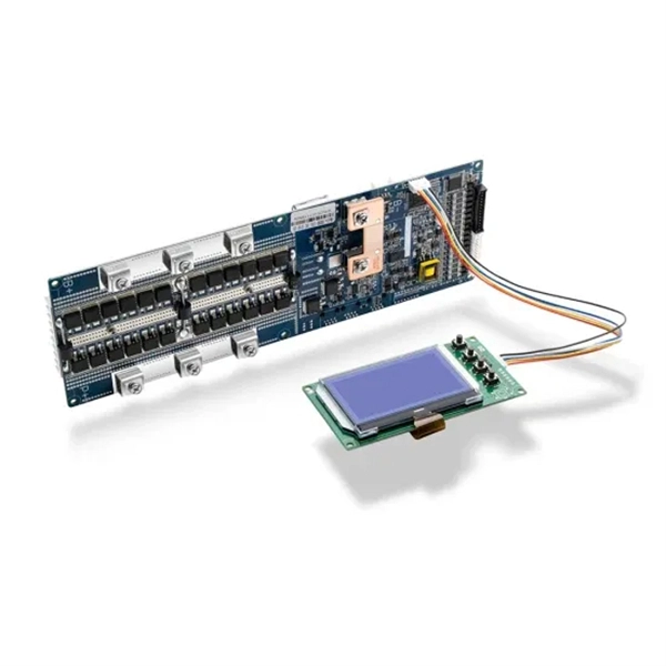
Installation Method of Electrical Components in Distribution Box
Comply with standards: Follow NEC, IEC, or local codes. Use UL/CE-certified parts and record installation details for future inspections. Schedule regular maintenance and inspections to ensure long-term reliability. Check for proper. Whether you are an electrical contractor or a construction brigade, knowing how to properly and safely install distribution boxes is the basis of ensuring the safe operation of the entire system. This article details the process of installing them, which helps you comprehend distribution boxes. Electrical systems power our homes, offices, and industrial facilities, but behind every reliable electrical setup lies a crucial component that often goes unnoticed: the distribution box. High voltage cabinet frame, bus, lightning arrester, high voltage porcelain bottle, voltage transformer, current transformer, various switches, etc. Over current relay adjustment, time relay.
[PDF Version]