-
Wiring of residual current circuit breaker in distribution box socket
In this video, I'll show you the complete wiring diagram of a home distribution board (DB). You'll learn how to connect the main circuit breaker (MCB), residual current device (RCD), and individual circuit breakers for lighting, sockets, and appliances. This guide provides a detailed, professional procedure for installing a Residual Current Circuit Breaker (RCCB)—a device essential for protecting people from the severe danger of electric shock. #dbbox #distribution #home #house. A distribution board or distribution box is where the main power supply is distributed to multiple loads. You will learn to build a safe, efficient, and professional electrical system today.
-
How to extend the wiring in a distribution box
Leave the receptacle wired, if wires are long enough to extend out to new position. Before you reach for a clumsy extension cord, consider a more permanent fix: extending electrical wire exactly where you need it. This creates a cleaner and safer setup. While the idea of extending electrical wiring can seem complex, it's based on a few core principles: shutting off the power. This specialized box provides a safe, contained space where the existing circuit wires can be physically joined with the new extension wires. more All My Favorite Tools: https://www. com/shop/everydayhomerepairsWAGO 221-413 or the 221-2401 make quick work of extending short wires.
-
Schematic diagram of trough-type cable tray
Legrand continues to be an innovator in cable management solutions and is proud to introduce Cablofil Trough Tray, a cable management system designed to maximize network reliability and minimize lifec.
-
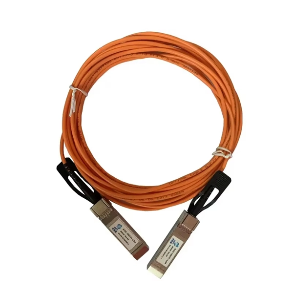
Home Fiber Optic Switch Connection Diagram
My network diagram. I came to the following requirement for my setup: In the end some of these didn't pan out as I will explain further down. I went with singlemode fiber with LC connectors in a G.657.
-
Calculation of wiring at the distribution box
Sizing the internal wiring correctly is accomplished by determining the maximum amperage (ampacity) the box will handle, which involves calculating the total connected load. For example, a 50-amp inlet requires a minimum of 6 AWG copper conductor for the main feeder wires (hot . A temporary power distribution box (TPDB), often called a spider box, functions as a portable electrical hub that centralizes and protects power distribution on a job site. Calculate proper wire gauge, voltage drop, and ampacity for safe electrical installations. Our goal? Make sure you never notice it. Before we dive into calculations, let's get familiar with a few essentials: 1. It takes the incoming power and safely distributes it to different circuits throughout your building.
-
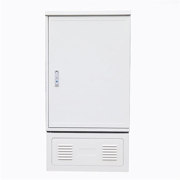
Comparison of Upgraded Wall-Mounted Wiring Box with Which One Offers Better Reliability
Finding the best electrical boxes for your home renovation or redo is vital. The right material, type, and size can increase security while eliminating the risk associated with house fires due to short circuit pr.
-
Wiring method for circuit breaker in distribution box
This guide shows you how to organize circuit breaker wiring properly. You will learn to build a safe, efficient, and professional electrical system today. Circuit breaker wiring configurations involve organizing main switches, busbars, and branch breakers within a distribution box. Messy distribution boxes are dangerous and very hard to fix. Breaker Panels may have different.
-

Cable Wiring Standards for Integrated Cabinets in Different Areas
This pocket guide provides an overview of the requirements for the installation of cables concealed in structures in accordance with regulation group 522. 6 of BS 7671:2018+A2:2022 (IET Wiring Regulations 18th Edition). In the industrial sector, electrical cabinets play a crucial role in distributing, protecting, and controlling electrical power. The NFC 15-100 standard is the primary benchmark. Running electrical wiring inside kitchen cabinets requires balancing aesthetic goals with strict safety and electrical code requirements. Cabinets are often the only way to route power to modern conveniences without opening walls, making this a common necessity in remodeling and new construction. Jump directly to This guide is intended to assist code authorities, installers and contractors in determining the suitability of UL Certified, Listed. This handbook is provided for the use of all Departments of the ITER Organization and is addressed primarily to system specifiers, designers and users of electrical components in otherwise non-electrical plant systems, rather than to designers of the power supply systems.
[PDF Version]
-
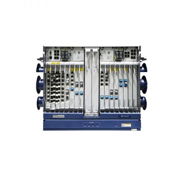
What are the different types of communication wiring units
Telecommunication cables encompass a wide range of types, including electrical cables, transmission lines, optical fibers, signal cables, and data cables. These cables serve as the backbone of modern telecommunications networks, enabling the transmission of data over long. When you talk about communication cable assembly, RF communication wire, or a communication wire harness, you're delving into a range of types each optimised for specific purposes. In this article we'll explore major categories, highlight their characteristics and typical uses—especially for. What are the different types of network cables? The main types of network cables are coax, fiber optics, and shielded and unshielded twisted pair. As enterprises deploy new technologies, it's critical to select the right cables. Selecting cables is a crucial part of network design.
[PDF Version]
-
Power Cable Tray Installation Steps
Step-1: Confirm the actual layout, dimensions & mounting height of cable trays & conduits. Step-3: Coordinate with other trades to prevent interference during installation. Article Summary: A compliant cable tray installation requires a thorough understanding of NEC Article 392, proper structural support, and precise installation techniques. The Cable Tray ng standards, performance standards, test standards and application in this document have been tested extens ompetent professional en completely installed, without damage either to conductors or. Here is a step-by-step guide on how to install a standard metal cable tray system (e. This guide covers copper and aluminum conductors from No. 14 AWG though 1000 kcmil, insulated for operation from 600 volts though 35 kilovolts.
-
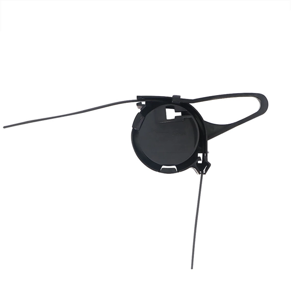
Steps for sealing vertical shaft cable trays
Spring knot is used to connect cable tray or trunking to channel. Approved and correct fittings are used. Installed containments are free of damages. maintain spacing or to keep cables in place when the tray is ect the minimum bend ra-dius for cables as they exit the bottom of the cable tray. A rung spacing of 6 to 9 inches (150 to 230 mm) is preferable when the cable tray cont d for instrumentation and control applications that require. What materials are available to make a watertight penetration through the top of a concrete pull box for a vertical run of cable tray? In practice, is it preferable to use PVC conduit with rubber pipe sleeves? My preference is to exit horizontally and use a ninety to go vertical. The Cable Tray system is installed in electrical rooms, plant rooms, and service. Tools and equipment needed for cable tray support installation should be in good condition and must be checked by Supervisor / Safety Engineer prior to use in the construction area.
[PDF Version]