-
Analysis of Optical Module Sensitivity Issues
This guide provides a comprehensive overview of sensitivity analysis in optical design. It involves analyzing how the performance of an optical system varies in response to changes in its design parameters. For example, SONET specifies that the BER must be 10 -10 or better. By understanding the measurement standards, influencing factors, and application. It is often useful to analyze your tolerances in detail so that you can best understand where and why sensitivities exist in your optical system. In OpticStudio's tolerance analysis, you may save the tolerance results for each Monte Carlo file, or you may save each tolerance in the sensitivity.
-
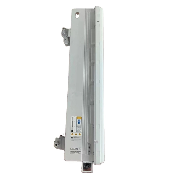
Optical Module Base Design
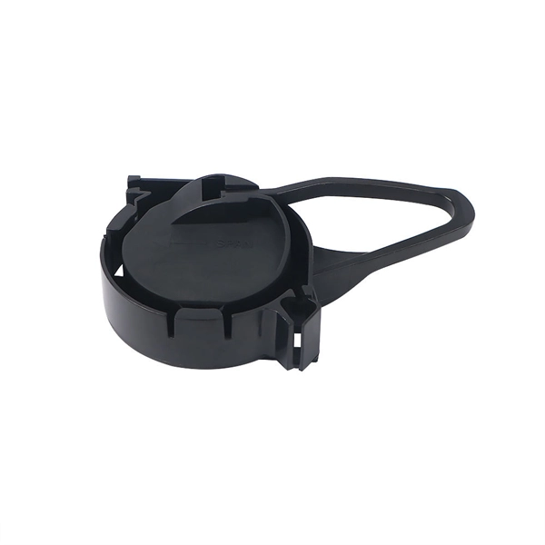
Optical module usually consists of a transmitter assembly (TOSA, containing a laser LD chip), a receiver assembly (ROSA, containing a photodetector PD chip), a driver circuit, an optoelectronic interface, a heat sink (some models), a housing, a pull ring and so on. Integrated circuits and reference designs help you create a smaller and faster optical module design used in high-bandwidth data communication applications. Whether you are creating a 100-Gbps or 400-Gbps, small form-factor pluggable (SFP) module, SFP+ transceiver, XFP module, CFP, X2/XENPAK module. Designing and producing these complex PCBs presents formidable challenges, requiring a convergence of disciplines—from high-frequency signal integrity and advanced thermal management to micron-level mechanical precision. These three laser diodes are described in more detail. contact us product page Copyright © 2024 MVSLINK. Critical Metrics: Signal integrity (insertion loss, return loss) and thermal management are the two.
[PDF Version]
-
MEMS optical switch design
In figure 1.2 a row of protection switches is shown that is used in parallel optical connections (e.g. bus connections between computers). All channels have to be switched at the same time to reroute the signals from one computer to ano. In figure 1.2 a row of protection switches is shown that is used in parallel optical connections (e.g. bus connections between computers). All channels have to be switched at the same time to reroute the signals from one computer to another. Protection switching is required to avoid a permanent interrupt of a connection due to fiber break or due to. mirror / shutter surface micromachining Si-On-InsulatorElectromagnetic actuators are used in optical switches, as these actuators are known from precision machined solutions and the actuating part is a simple coil of many turns of wire. The ferromagnetic materials required in microsystems can easily be realized by sput-tering or electroplating of Permalloy. Additionally, the combination of permanent ma.
[PDF Version]
-
Analysis of the causes of signal attenuation in optical splitters
In the context of beam splitters, attenuation can occur due to several factors, including absorption, reflection, and scattering. Understanding how beam splitters affect signal attenuation and polarization is essential for optimizing systems in telecommunications, imaging, and laser applications. In the. Fiber optic splitters distribute optical power from one input fiber to multiple output fibers through either fused biconical taper (FBT) coupling or planar lightwave circuit (PLC) waveguide structures. Their performance depends on optical symmetry, waveguide integrity, and mechanical stability of. · Signal Attenuation: The loss of signal strength as it travels through the fiber can lead to poor quality communication. By careful processing, couplers that were bidirectional were made. So a 2:2 coupler would take the signal from one fiber on one side and split it between the two fibers on the.
[PDF Version]
-
Principles and Product Design of Optical Fiber Communication
Optical Fiber Communication (OFC) revolutionizes modern telecommunications, enabling rapid data transfer across long distances with minimal signal loss. This comprehensive review explores OFC's historical evolution, core principles, components, and versatile applications. Kanade Department of Electronic-Science, P. College of ASC, Pravaranagar, India fPublished. The digital communication techniques discussed so far have led to the advancement in the study of both Optical and Satellite communications. Light acts as a carrier wave and can be modulated to carry information. Higher bandwidth (extremely high data transfer rate).
-
Underground Depth of Optical Cable
Fiber optic cables are typically buried between 12 and 36 inches (30–90 cm), depending on installation environment, soil conditions, and load requirements. In high-load areas such as roads or backbone routes, burial depth can reach 48 inches (120 cm) or more. With international fiber networks predicted to grow to over 1. 8 million km in scope by 2025 (per TeleGeography), burying these cords of light comes with the benefits of avoiding cable damage, decreasing downtime, and extending their operational lifetime. For broader context on underground. Underground cables are pulled in conduit that is buried underground, usually 1-1. 2 meters (3-4 feet) deep to reduce the likelihood of accidentally being dug up. In extreme cold climates, cables may need to be buried at greater depths where there temperatures are colder and frost penetrates to. Estimate minimum burial depth (cover) for underground electrical, fiber, and low-voltage cable runs using a practical, code-aware ruleset. Always consult local utility regulations and obtain necessary permits before excavation.
[PDF Version]
-
Hazards of Laying Optical Cables
Optical fibers, though renowned for their efficiency and bandwidth, aren't immune to risk factors that could spawn safety hazards. The very nature of fiber optic cabling requires handling microscopic strands that, when damaged, can cause signal loss or, worse, physical harm. Understanding the safety hazards that go with fiber optic cable is critical for those who install or maintain fiber optic systems. As electrical professionals, most of us take fiber optic (FO) safety for granted. Recognizing the potential safety hazard inherent in the installation and maintenance of optical fibers is crucial to mitigating risks of personal or property damage. Know the standards that apply to your work Whether you're installing new fiber optic cables or troubleshooting and repairing an existing fiber network, a working knowledge of the regulations that apply to your. However, fiber optics installation is not without risks. Even the output of OTDRs, WDM and fiber amplifier systems, which are. Working with fiber optic cabling requires precision, skill, and a strong understanding of cabling safety.
[PDF Version]
-
North Macedonia Optical Line Terminal 10G
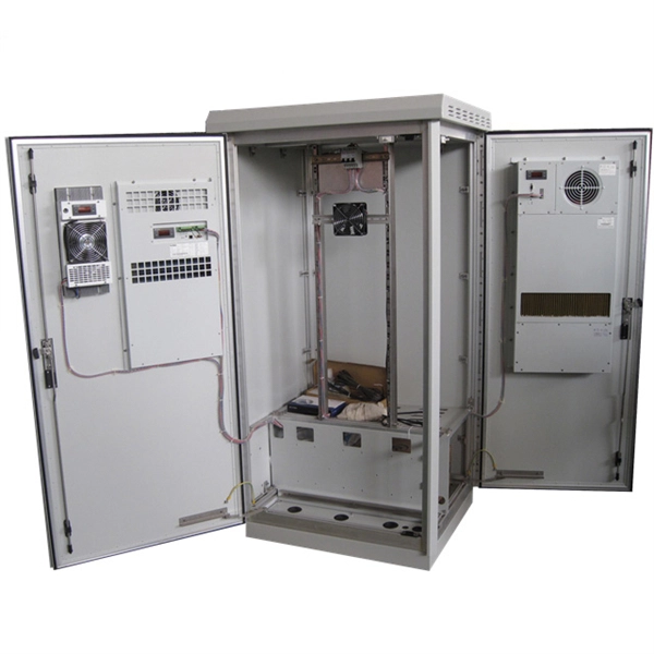
The 10G SFP+ LR Ethernet Line optical transceiver transmits data over single mode fibre at a distance of up to 10km. The transceiver operates on 1 wavelength and works in point-to-point scenario. Modern OLTs offer communication service providers (CSP) the ability to launch multigigabit services to tens of thousands of subscribers from a single location or just ten. Fiber-to-the-home. HA7308VX is a small capacity 8 port OLT device launched by HiOSO. It can be used with HA7200 series ONU and passive optical distribution network (ODN) to form a passive optical network to achieve performance management, fault management, and configuration management of the equipment. 5G/5G/10GBase-T Multi-rate SFP+ Module (Twisted Pair Category Cable, 100m 1G/2. 5G Cat5e, 70m 5G Cat5e, 30m 10G Cat6a/7, RJ-45, C-temp) Specifications Form. Field-proven EPON and 10G-EPON OLT SoC solutions Cortina family of Optical Line Terminal (OLT) SoCs completes the end-to-end solutions for EPON and 10G-EPON applications.
[PDF Version]
-

Function of rack-mounted optical amplifier splitter
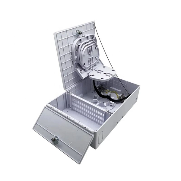
Designed to house multiple fiber splitters in a single rack unit, these devices simplify signal routing and help keep your network structured — without sacrificing valuable space. Rack-mount fiber optic splitters are passive optical splitters integrated into standard rack-mounted chassis, typically installed in telecom racks, ODF frames, or central office distribution systems. Unlike compact module splitters placed inside terminal boxes, rack-mount splitters are designed for. VOYGAR provides ABS Cassette PLC Splitter family has 1x2, 1x4, 1x8, 1x16, 1x32, 1x64, 2x2, 2x4, 2x8, 2x16, 2x32,2 x 64 PLC splitter, with specifications that are tailored for different applications and markets. The structure of rack chassis PLC splitter is to install. Fiber Optic PLC Splitter is an essential passive component in Fiber to the Home network.
-
What is the appropriate height for optical fiber cables
Based on my first-hand, environmental testing of the declination of the ceramics under pressure and under temperature, I recommend targeting a fiber height of +/-20 nanometers. The Fiber Optic Association, Inc. (FOA) was founded in 1995 to help develop the workforce to build the fiber optic networks to support a rapid expansion in communications and the Internet. The charter of the FOA was to promote professionalism in fiber optics through education, certification, and. Fiber height is a critical geometry parameter (along with Radius, Angle/Apex, and Key Error), which directly impacts the optical performance of the connector in the fiber optic network. Failure to follow these guidelines may result in damage or attenuation increases of the optical fiber or cable. Proper industry. cations, security, control and similar purposes. FO-VC2 JOINT USE - VERICAL MIDSPAN CLEARANCES 48.
[PDF Version]
-
Which port on the switch is the optical interface
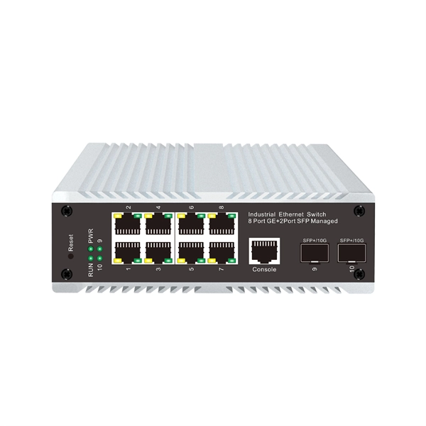
The optical port of an industrial Ethernet switch refers to the optical fiber interface, which has single-mode, multi-mode, gigabit, and gigabit specifications. Port types are limited to two: optical and Ethernet. RJ45 ports serve access-layer copper connections; SFP/SFP+ ports enable flexible 1G/10G uplinks; SFP28 delivers 25G for modern data centers; QSFP+ and QSFP28 support high-density 40G/100G spine–leaf. GBIC is an interface device that converts gigabit electrical signals into optical signals. This design enables end-to-end optical signal transmission, avoiding the conversion between electrical and. The optical ports on the switch are usually paired together, with one TX sender and one RX receiver. The. Most SFP fiber optic modules use LC connectors, while SC connectors are mainly found in legacy networks and MPO/MTP connectors are used for high-density cabling rather than directly on standard SFP modules. This connector landscape reflects how modern SFP deployments prioritize port density and.
[PDF Version]
-
10 Gigabit Ethernet card optical module not connected to fiber optic cable
Troubleshooting SFP+ link issues in 10 GbE networks requires attention to module type, match of speed and wavelength, clean fiber connections, correct configuration, thermal management, and equipment compatibility. You can quickly resolve SFP+ Module connectivity issues by following a systematic optical transceivers troubleshooting process. Check for common connection problems, such as link failures or modules not recognized. Check compatibility between the optical module and switch Most switch brands have specific compatibility requirements. During network upgrades, many enterprise users encounter a common issue: after replacing 10G broadband lines or inserting 10G SFP+ optical modules, the switch still fails to operate at full 10G bandwidth or even fails to recognize the modules. We've listed the five most common ones. First of all, let's briefly recap what SFP and SFP+ stand for. SFPs – short for 'small form-factor pluggable' – are compact, hot-pluggable devices.
[PDF Version]