-
1-meter wide cable tray support spacing
Generally, standard trays require supports every 6 to 10 feet, while heavy-duty, long-span trays can handle distances of up to 20 feet between supports. To determine the proper spacing, consult the manufacturer's load capacity chart, which accounts for the total weight of the. The NEC requires that cable trays must be supported by members at an interval specified by the cable tray manufacturer, but not more than 5 feet for horizontal runs to support the weight of the cables and other loads. The NEC has a requirement for ladder-type cable trays. The rungs cannot be more. en completely installed, without damage either to conductors or structural system use maintain spacing or to keep cables in place when the tray is ect the minimum bend ra-dius for cables as they exit the bottom of the cable tray. Proper installation can significantly reduce electromagnetic interference, prevent fire hazards, and improve overall efficiency. This article provides an in-depth. Ladder cable tray is available in widths of 6, 9, 12, 18, 24, 30, 36, 42 and 48 inches with rung spacings of 6, 9, 12 or 18 inches. The Ladder Tray features light, rugged, tubular steel construction.
[PDF Version]
-
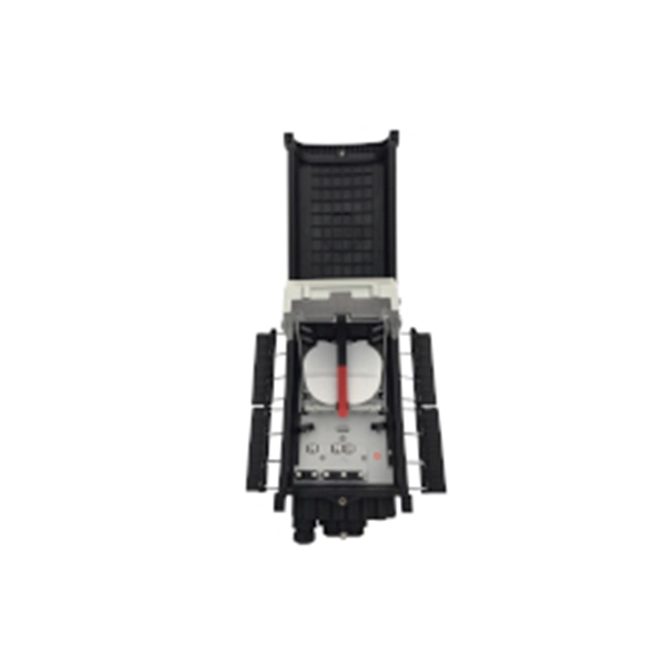
List of Congo optical cable protection units
This is a list of international. It does not include, such as those on the coastlines of,, and. All the cable systems listed below have in two or more countries. Several older cables are no longer used for international telecommunications, but are used for scientific purposes. Others are simply abandoned.
-
How much distance should there be between the cable tray and the side support
For horizontal sections where cable trays are laid out in a straight line, the typical support span (distance between supports) should range from 1. This range allows for easy access and efficient maintenance. The NEC requires that cable trays must be supported by members at an interval specified by the cable tray manufacturer, but not more than 5 feet for horizontal runs to support the weight of the cables and other loads. According to the regulations under NEC 392. 10 (B) (1), the smallest size single conductor allowed to be installed in a cable tray is 1/0 AWG. For the installation of single conductor cables sized 1/0 AWG to 4/0 AWG in industrial establishments, the NEC specifies the maximum allowable rung spacing for the cable. Unlike a simple wire trough, which is typically a covered channel for shorter runs, cable trays provide a comprehensive support system for complex wiring paths over long distances. A well-planned cable tray installation not only organizes conductors but also provides protection and makes future.
[PDF Version]
-
How to calculate the support structure for steel cable trays
Cable tray support quantity can be calculated using a simple formula: Support Quantity = Total Length ÷ Support Spacing + 1 20 ÷ 2 + 1 = 11 supports In a typical project, a 20-meter cable tray with 2-meter spacing requires 11 supports. As a key structure supporting the cable tray, the accurate calculation of the support quantity directly affects construction costs, efficiency, and safety. In complex engineering environments, the. This guide covers the critical steps, from selecting the right electrical cable tray and performing accurate cable fill calculations to managing a safe cable pull through and ensuring all bonding and grounding requirements are met. Ideal for electrical contractors and engineers. Classification of Loads Cable tray loads can be classified into the following categories: Dead Load (G): This. Correct sizing prevents sagging, overheating, and premature failure. You don't need a PhD—just a consistent method. This step‑by‑step approach helps you determine width, depth, support spacing, and allowable load with confidence.
[PDF Version]
-
How much distance should the cable tray support be installed
Generally, standard trays require supports every 6 to 10 feet, while heavy-duty, long-span trays can handle distances of up to 20 feet between supports. To determine the proper spacing, consult the manufacturer's load capacity chart, which accounts for the total weight of the. The NEC requires that cable trays must be supported by members at an interval specified by the cable tray manufacturer, but not more than 5 feet for horizontal runs to support the weight of the cables and other loads. The NEC has a requirement for ladder-type cable trays. This spacing is crucial for adequate maintenance access, ease of inspection, and ensuring proper airflow for effective heat dissipation. Support Methods: Common support methods include trapeze hangers, which are. This is a description of how to select, install, and support these metal or plastic frames, on which electrical wires are installed.
[PDF Version]
-
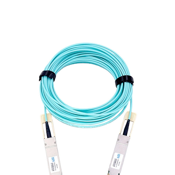
Fiber optic cable does not support 1550
Multimode fiber is designed to operate at 850 and 1300 nm, while singlemode fiber is optimized for 1310 and 1550 nm. One of the major advantages of 1550 nm transmission is compatibility with Erbium-Doped Fiber Amplifiers (EDFA). All Singlemode fibers work very similarly in either wavelength—that is, you don't need to buy fiber based on wavelength, one fiber fits all. So, IF your cable assembly is built. This article delves into why 850, 1310, and 1550 nm are standard, what less-known regimes and tradeoffs exist, and how an OEM fiber-cable manufacturer can design and test with wavelength considerations built in. Consider the balance between attenuation and dispersion when designing your network for optimal performance.
-
Invisible fiber optic cable can be connected to a network port panel
The short answer is no - RJ45 connectors are designed for electrical Ethernet signals, while fiber optics transmit light pulses through glass or plastic. However, modern networks often combine both technologies. In this article, we'll explore the ins and outs of FTTR Invisible. There are endless ways to configure a fiber-optic network, but here are a few simple ways to add fiber to your existing network., Cat 6a) to fiber and back again. If category cable is used, doesn't that negate the benefits of the fiber? Fiber provides a much cleaner installation due to its size and is 'future proof'.
-

Cables without armor are run in cable trays
The cables identified as Type TC-ER (Exposed Run) can be installed in industrial establishments for the connections between the cable trays and the equipment without metal conduits or armored cables Type MC (Metal Clad Cable); this kind of connections is called Open Wiring. Type TC – Tray Cable – (NEC Article 336) –Power and control tray cable type TC is a factory assembly of two or more insulated conductors, with or without associated bare or covered grounding conductors, under a non-metallic jacket. Pictured here are:. UL Listed shielded cables (THHN/THWN or TFN) built for the uses specified by art. 336 of ANSI/NFPA 70 “National Electrical Code” (NEC) and suitable for use in Class I, Division 2, Hazardous Locations. 8 meters (6 ft) of cable extends from the tray for a connection to a motor or other electrical device, cables without an ER rating must be either armored (type MC) or installed in conduit or another. Tray cable types TC, ITC and PLTC are permitted in cable trays by the NEC. CEC 12-904 (2) indicates that no raceway shall contain conductors of a different source unless they have metal armor.
[PDF Version]
-
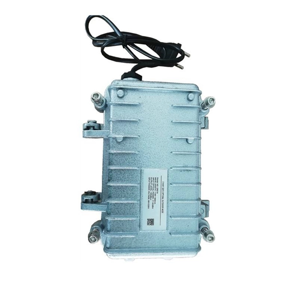
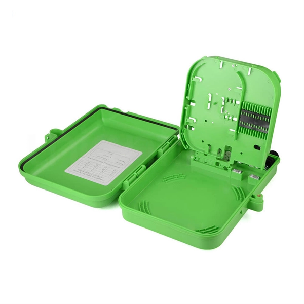
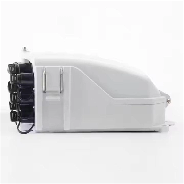
Protection Measures for Optical Cable Line Engineering
Optical cable lines lightning protection and strong current protection are achieved by avoiding, guiding or discharging them underground to prevent lightning and strong current from causing damage to the optical cable lines themselves, communication equipment and personnel. Since the lightning. The Fiber Optic Association, Inc. The conduit can be made of various materials such as PVC, HDPE, or steel. It is suitable for areas with flat terrain and small undulations. This type of fiber optic is laid in two ways: suspended under steel strand and self-supporting suspension. Local exchange carriers use fibres to carry the same service between central office switches at local levels, and sometimes as far as the neighbourhood or individual home.
-
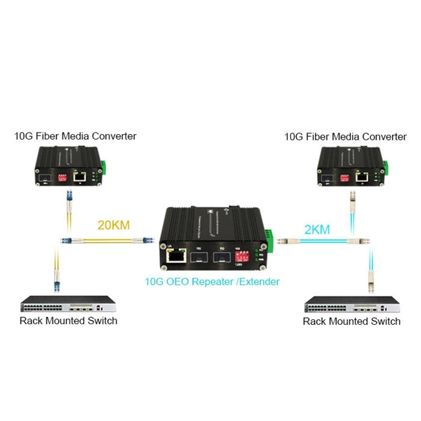
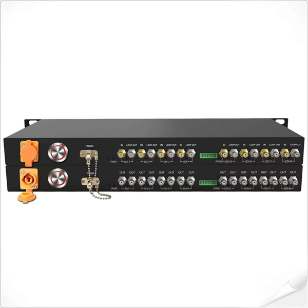
10 Gigabit Ethernet card optical module not connected to fiber optic cable
Troubleshooting SFP+ link issues in 10 GbE networks requires attention to module type, match of speed and wavelength, clean fiber connections, correct configuration, thermal management, and equipment compatibility. You can quickly resolve SFP+ Module connectivity issues by following a systematic optical transceivers troubleshooting process. Check for common connection problems, such as link failures or modules not recognized. Check compatibility between the optical module and switch Most switch brands have specific compatibility requirements. During network upgrades, many enterprise users encounter a common issue: after replacing 10G broadband lines or inserting 10G SFP+ optical modules, the switch still fails to operate at full 10G bandwidth or even fails to recognize the modules. We've listed the five most common ones. First of all, let's briefly recap what SFP and SFP+ stand for. SFPs – short for 'small form-factor pluggable' – are compact, hot-pluggable devices.
[PDF Version]