-
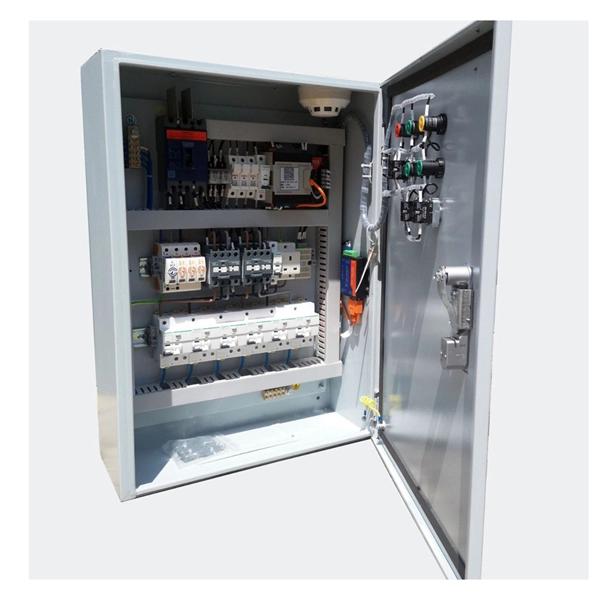
Lightning Protection Parameters for Photovoltaic Combiner Boxes
Technical Parameters:DC voltage shall not be lower than the system's highest voltage; circuit breaking capacity shall be at least 20kA to ensure that a faulty bypass is disconnected in 0. 1 seconds in the event of a short circuit. Summary: Discover how intelligent combiner boxes with lightning protection optimize photovoltaic system safety, reduce downtime, and improve ROI. Learn about critical components, industry trends, and why EK SOLAR's solutions stand out in global markets. Lightning strikes cause 7–12% of all. When selecting a photovoltaic (PV) combiner box, several key parameters must be considered to ensure the efficient operation and safety stability of the PV power station. This device plays a vital role in safeguarding solar installations from.
-

Relay Protection Test Wiring Method
One approach to test the total protection system is to use primary injection techniques (see appendix H) that trigger protective relays and lockout relay, trip circuit breakers, and initiate annunciations and indications. If applicable, documentation is required detailing how verified protection segments overlap to ensure there is not a gap. The purpose of this Standard Work Practice (SWP) is to standardise and describe the method for testing of Ergon Energy protection relays for commissioning purposes. This SWP should be interpreted in conjunction with Standard for Substation Protection (V1. From a technician's perspective, master the unique skill of testing protection. When the transformer wiring type is Y/Y (Y0), the test wiring is very simple: when testing phase A, the tester IA is connected to the phase A of the high voltage side, and the tester IB is connected to the phase a of the low voltage side. After the neutral line of the high and low voltage sides is. Function: Use electronic components like transistors to perform switching. Applications: Frequency, undervoltage, and overcurrent protection.
[PDF Version]
-
Is it dangerous to repair relay protection
Doing so may result in reducing Relay performance for insulation failure, contact welding, and contact faults, and might even result in burning or other damage to the Relay itself. Do not drop the Relay or dismantle it. Refer to the Safety Precautions for individual Relays for precautions specific to each Relay. Electric shock may. A relay that is correctly set for yesterday's system may become a serious risk after a plant expansion or load change. This article breaks down the most common protection relay misconfigurations in industrial facilities, why they happen, and how they impact system reliability and operational. onding to faults, ensuring the reliability and stability of the grid. However, unauthorised changes to protection relay settings pose a significant threat to the integrity of power systems. Although failure of a protective relay system may have severe local or regional impacts, most protective relay systems are not required to operate to prove they are in working order.
[PDF Version]
-
Requirements for Relay Protection Design
The IEEE standard for protection relays refers to a collection of guidelines developed by the Institute of Electrical and Electronics Engineers. This document provides recommendations, background and philosophy on relay protection that is not available in M07. They are intended to quickly identify a fault and isolate it so the balance of the system continue to run under normal conditions. For professionals working in utilities, industries, or renewable energy systems, understanding these standards is not optional—it is essential. This handbook covers the code of practice in protection circuitry including standard lead and device numbers, mode of connections at terminal strips, colour codes in multicore cables, dos and donts in execution.
-
Wired Channel for Relay Protection
With the addition of a line tuner, the CCVT (used for potential input to the protective relay) can be used to couple the PLC signal to the power line. Protection systems are used to isolate faulted parts of the system, protect the electric system from instability, and minimize equipment damage. Directional distance and overcurrent schemes, interfaced with communication equipment, send and receive logic-based information between relay te minals to determine if the fault is external or internal to the. Important benefits include limiting tripping to faulted line section, high-speed simultaneous clearing for all internal line faults, preventing overtripping on external faults, and reducing transmission line and station damage. Applications of the concepts to accepted transmission line-protection schemes are also presented.