-
How to calculate the size of a small electrical distribution box
The formula for calculating electrical box size is: [ BS = (N times D) + A ] Where: ( BS ) is the box size in cubic inches. ( N ) is the total number of conductors. This electrical box fill calculator (or in short, box fill calculator) will help you determine the total box fill volumes you will need to meet so that each of your electrical utility boxes will pass the National Electrical Code®. This guide explores the science behind determining the appropriate box size, providing practical formulas and expert tips to help you achieve accurate. Master electrical box fill calculations and ensure NEC compliance for safe and code-compliant electrical installations. Learn the principles, formulas, and best practices for proper wire management. ) Variables: To calculate the. Article Summary: Calculating the correct junction box size per the NEC 2023 involves a process known as a “box fill calculation,” primarily governed by NEC Article 314.
[PDF Version]
-
How many meters is the electrical cable tray
The straight length of an ordinary cable tray is generally 2 meters. However, other common lengths include 3 meters, 4 meters, and 6 meters. The formula used to calculate cable tray capacity is: Cable Tray Capacity = (Tray Width × Tray Depth × Fill Ratio) / Cable Cross-sectional Area Where: Tray Width is the internal width of the cable tray in meters (or millimeters). Tray Depth is the internal depth of the cable tray in meters (or. What is the fill capacity and remaining capacity of my cable tray? Calculate cable tray sizing and fill capacity based on tray dimensions, cable diameter, number of cables, and maximum fill percentage per electrical code. This committee has published three documents to date: NEMA VE1, FG1 and VE2.
-
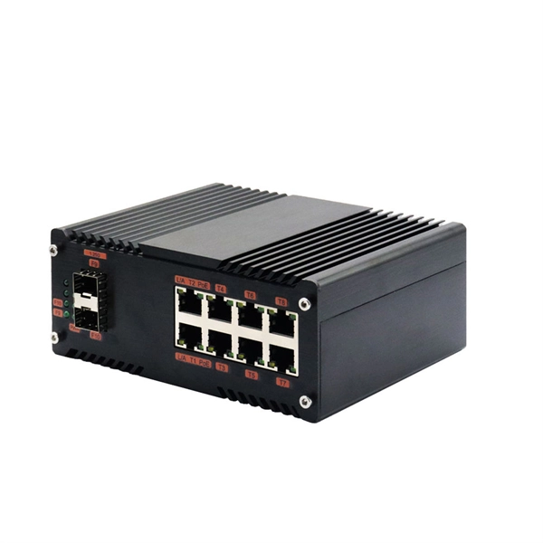
How to convert an electrical port to an optical port on a switch
A switch SFP port converts electrical signals into optical signals via SFP transceivers, or maintains them electrically for copper connections. By using an SFP to RJ45 adapter (e. 5G SFP), you can seamlessly connect legacy Ethernet devices to modern fiber-optic. The RJ45 port is a built-in electrical port of a Gigabit Ethernet switch, and it is mainly connected by Category 5, Category 5e, Category 6, and Category 6e twisted-pair cables. However, modern networks often combine both technologies. The good news: you can bridge them easily using the right hardware, such as media. An SFP port on a switch or router SFP port enables network engineers to connect multiple media types, from fiber optic links to copper Ethernet. An SFP transceiver acts as a compact, hot-swappable optical transceiver that.
-
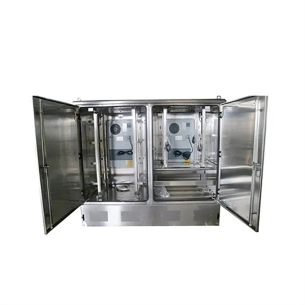
Each room has an electrical distribution box
Larger circuit breakers may also connect to secondary panels, called subpanels. Subpanels have their own set of circuit breakers and power specific appliances or areas of the house. A subpanels is often locat.
-
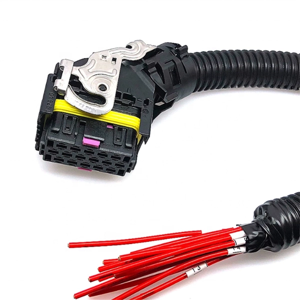
How to test a properly spliced optical cable
The most common methods for testing fiber optic splices are optical time-domain reflectometry (OTDR) and optical loss test set (OLTS). For every fiber optic cable plant, you will need to test for continuity, end-to-end loss and then troubleshoot the problems. If it's a long outside plant cable with intermediate splices, you will probably want to verify the individual splices with an OTDR also, since that's the only way to make. That's where splicing comes in—and knowing how to properly splice a fiber optic cable is a critical skill for any technician. Splicing allows you to restore or expand fiber networks while maintaining signal integrity. Fiber optic testing of a newly installed system not only verifies that the system meets its design requirements, but also creates a performance baseline for all future testing and troubleshooting of t at system.
[PDF Version]
-
How to quote prices for electrical distribution box wiring and accessories
Include everything: wire, boxes, devices, connectors, tape, wire nuts, and consumables. Update quarterly as prices change. Add your material markup (typically 20-50%) and apply your labor rate to the time estimate. Win more electrical contracts with professional quotes that close deals faster. Whether you need an electrical quotation for house wiring or a commercial electrical quote template for larger projects, this electrical work quotation form handles it all. Average markup 30-50% on materials. Calculating material costs, labor fees, and profit margins for electrical projects can be challenging, especially when meeting client expectations or managing revisions. This template helps electricians prepare estimates for wiring, repairs, or installations in homes and. In this guide, we'll go through the main steps in the electrical estimation process, helping you navigate these challenges to improve your project bids.
[PDF Version]
-
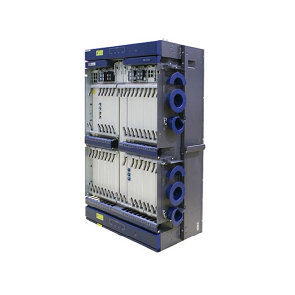
Troubleshooting Checklist for Fan Room Electrical Distribution Box
Check for any tripped breakers or blown fuses and replace them as necessary. Inspect and clean contacts to maintain good electrical conductivity. Internal Inspection Open. It is strongly recommended that the Air Movement and Control Association International Inc. (AMCA) Publication 202 “Troubleshooting” and AMCA Publication 410 “Recommended Safety Practices for Users and Installers of Industrial and Commercial Fans” be thoroughly read prior to any investigation. Power Distribution Unit (PDU) 1). LV Intrusive Switchboard Low-voltage intrusive switchboards regulate and distribute power in buildings and facilities. Be sure to have your badge scanned by a room monitor so a complete attendee. Check for any signs of damage, wear, or overheating in electrical panels, switchgear, transformers, and other equipment.
-

Does the elevator machine room necessarily need a separate electrical control box
Each car, machine room and hoistway pit must have separate dedicated branch circuits for lighting, receptacles and HVAC, with car and machine-room lighting exempt from GFCI while required for receptacles. Overcurrent devices and disconnects must be located in machine or control spaces, be lockable. Provide a legally constructed and enclosed control room, adequately lighted, and conditioned to maintain temperature between 60° to 90° Fahrenheit, relative humidity is not to exceed 90% non-condensing. Control room must be of adequate size to provide clearances around and between equipment as. Main Power Circuit: Typically, a 240VAC, 30 Amp dedicated line with 10/3 copper wiring (including a dedicated neutral and ground) serves the elevator motor and controls. This is always an isolated circuit, never shared. Typically, for residential elevators, a machine room will be located on the lowest landing as close as possible to the elevator hoistway. These systems eliminate the need for a separate room to house hydraulic pumps, control panels, etc. However, they do present some challenges.
[PDF Version]