-
Fiber optic cable connected to router but no internet speed
Restarting your router is one of the easiest ways to resolve minor internet speed issues. Often, these devices just need a fresh reboot to clear out temporary glitches and restore your connection to full speed. Wait for about 60 seconds to make sure it fully. Fiber optic networks are celebrated for their speed and reliability, but even the best systems can encounter problems. In many cases, a fiber connection problem originates from one of the following. However, the Data LED is specific to your home network, so if the LED is off, check the Ethernet cable or the router. Fiber, cable, and DSL are wired internet connections, so the best way to check their speeds is to use an Ethernet connection and a wired device. However, despite their remarkable capabilities, fiber.
-
Will fiber optic pigtail damage affect internet speed
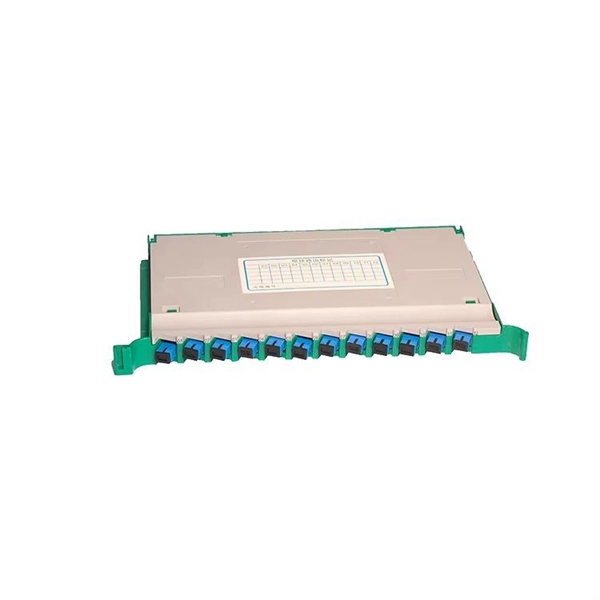
However, when signal loss occurs in a 12 fiber pigtail, it can lead to disruptions in network performance, such as decreased data transfer speeds, increased error rates, or even complete outages. Executive Summary: A fiber optic pigtail is one of the most commonly specified yet least understood components in structured cabling. Get the wrong connector type, the wrong polish, or skip proper fusion splicing technique—and you're looking at elevated signal loss, increased back reflection, and a. Fiber optic networks are celebrated for their speed and reliability, but even the best systems can encounter problems. When issues like signal loss, slow speeds, or intermittent connectivity arise, systematic troubleshooting is key. Designed to transmit data using light pulses, these cables offer exceptional speed, bandwidth, and reliability. While these cables are engineered for durability (with some rated to last 25+ years), they are not invulnerable. Signal Loss (Attenuation) One of the most frequent problems in fiber optic networks is signal loss —the.
[PDF Version]
-
Cooperation with the Ministry of Energy and Internet
IA coordinates the U.S. Government's international energy relationships with foreign governments and energy ministries, working in concert with the Departments of State, Defense, Treasury, Interio.
-
How to test the continuity of pigtail fiber
A visual fault locator (VFL) makes use of a visible spectrum laser light to test the continuity of the fiber and detect fault conditions. There are two reasons we may want to test bare fiber, by that we mean fiber that has not been terminated in connectors but is simply plain optical fiber, The first one is to ensure the fiber or cable being manufactured meets its specifications, as is done by every manufacturer. Fiber optic. The Optical Time Domain Reflectometer (OTDR) will be used to test splice loss and to conduct span analysis. An Optical Power Meter and Laser Light Source will be used to measure power loss on each completed ring or distribution span to verify continuity between fibers (no fibers incorrectly spliced. A visual check is often the first step when diagnosing a defective fiber pigtail. Continuity testing verifies that the fiber is intact and that light can pass through from one end to the other without any blockages. This comprehensive guide will equip you with the knowledge and skills to accurately assess the integrity of a pigtail, helping you identify issues.
[PDF Version]
-
Relay Protection Test Wiring Method
One approach to test the total protection system is to use primary injection techniques (see appendix H) that trigger protective relays and lockout relay, trip circuit breakers, and initiate annunciations and indications. If applicable, documentation is required detailing how verified protection segments overlap to ensure there is not a gap. The purpose of this Standard Work Practice (SWP) is to standardise and describe the method for testing of Ergon Energy protection relays for commissioning purposes. This SWP should be interpreted in conjunction with Standard for Substation Protection (V1. From a technician's perspective, master the unique skill of testing protection. When the transformer wiring type is Y/Y (Y0), the test wiring is very simple: when testing phase A, the tester IA is connected to the phase A of the high voltage side, and the tester IB is connected to the phase a of the low voltage side. After the neutral line of the high and low voltage sides is. Function: Use electronic components like transistors to perform switching. Applications: Frequency, undervoltage, and overcurrent protection.
[PDF Version]
-
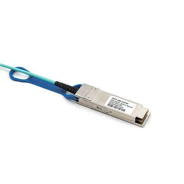
Optical module test power not adjusted too low
What does it mean if the transmitted power is too low? Low transmitted power can mean the connectors are dirty. Clean the connectors, check the module, and look at the fiber. If it still does not. Stable optical power is the foundation of every high-capacity optical transport system. Even minor deviations—whether too high, too low, or unstable—can impact signal integrity, trigger service alarms, or interrupt traffic on DWDM, OTN, or long-haul optical line systems. Because optical networks. The article Digital Diagnostic Function (DDM) For Optical Modules describes that DDM function can be used for real-time monitoring and fault location of the module's working status, in which the optical module's transmitting optical power and receiving optical power are the key parameters for. To test transmitted power in sfp optical modules, you use an optical power meter to get exact results. Many sfp modules also have DOM/DDM, which lets you see digital diagnostic monitoring data on network equipment. Built into modern SFP/SFP+/ SFP28 /QSFP family modules and standardized by SFF-8472, DDM/DOM exposes real-time values for the module's temperature, supply.
[PDF Version]
-
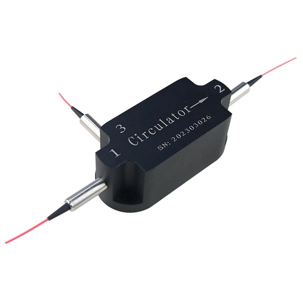
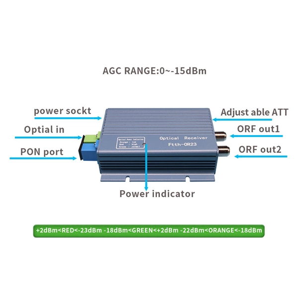
How to test a 1 2 beam splitter
To accurately measure optical splitter loss, utilize optical test equipment like power meters and spectral analyzers. Here's how: Measure the optical power at both the input and output ports of the splitter. What are Optical Splitters? The fiber optic splitter is a device used in fiber optic networks to divide a single optical signal into multiple signals. A beam splitter or beamsplitter is an optical device that splits a beam of light into a transmitted and a reflected beam. In its. This article explains how to create a beam splitter cube in Sequential Mode. Note that jT j2 is the transmitted intensity. I have been looking and either I can't find what I am looking for, or I just get. Page 5 Outline of Product Manual Outline of Product Manual The entire documentation of the hydraulic stone and concrete splitter includes: Product Manual – Information Manual (IM) – for the operator of the device – Operating Manual (OM) – for the operator and –. Table of Contents (IM) Table of.
[PDF Version]
-
Distribution Box Ground Resistance Test
The selective testing method uses one clamp and two stakes. It allows you to measure the ground resistance at specific parts of an installation, isolating the system to check or reference what's in place. Th.
-
Test Report on a New Vertical Cavity Surface Emitting Laser
Recent results on highly reliable 940nm multi-junction high power vertical-cavity surface-emitting lasers (VCSELs) are presented with target applications in depth sensing and Light Detection Ranging (LiDAR) markets. Vertical-cavity surface-emitting lasers (VCSELs) having a small aperture and operating in a single transverse mode (SM) are known to reach high relaxation oscillation frequencies of 30-90GHz and, thus, can offer intrinsic modulation bandwidth beyond 100GHz, once photon damping and electric. In this work, we present a high-performance vertical cavity surface emitting laser (VCSEL) based on a single-crystal CsPbBr 3 microplatelet, fabricated through a simple solution process and sandwiched between two distributed Bragg reflector (DBRs). Our innovation, the antireflective.
-
Multimode optical cable test length requirements
The cable should be longer than either of the following specifications, Event Dead Zone or Loss Dead Zone and the pulse length being used. Corning recommends that all fiber optic systems be tested to a minimum set of standards. So, you drop everything and i vestigate. He's right – it is n t working. Link testing of multimode segments should be done with an 850/1300nm dual wavelength unit. Since there is not an IEC/EIA. The length of launch cable used can very depending on the measurement needs. NEIS® are intended to be referenced in contrac documents for electrical construction ation or liability to users of this publication. Existence of a standard shall not preclude any member or nonmember of NECA or FOA from specifying or using. Other than for short-reach single-mode applications that are more susceptible to reflections and take connector reflectance into consideration, insertion loss testing, length, and polarity are really all you need for Tier 1 certification testing. Measured in decibels (dB), insertion loss is the. ANSI/TIA‑568.
[PDF Version]
-
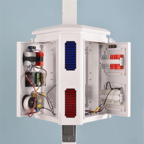
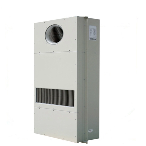
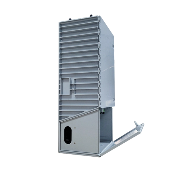
What are some commonly used devices in network cabinets
These include routers, switches, servers, patch panels, and solar batteries. Network server cabinets are the backbone of modern IT infrastructure, housing critical components that enable data processing, storage, and communication. A well-designed server cabinet optimizes space, cooling, security, and accessibility, ensuring reliable operation in environments ranging from. What is a Network Cabinet? 1. From the ubiquitous routers that serve as the traffic directors of the network to the versatile switches that enable efficient data transmission, we'll unravel the mysteries behind these devices and unveil the. Network Devices are the physical appliances required for communication and interaction between computers on a computer network. Allow devices to connect to networks efficiently and securely.
-
Internal relays of relay protection devices
The fault can be located upstream or downstream of the relay's location, allowing appropriate protective devices to be operated inside or outside of the zone of protection.OverviewIn, a protective relay is a device designed to trip a when a is detected. The first protective relays were electromagnetic devices, relying on coils operating on moving par. Electromechanical protective relays operate by either, or. Unlike switching type electromechanical with fixed and usually ill-defined operating voltage thresholds. Electromechanical relays can be classified into several different types as follows: "Armature"-type relays have a pivoted lever supported on a hinge or knife-edge pivot, which carries a moving contact. These relays may.