-
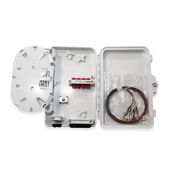
Internal Components of the Distribution Box for Low Voltage Electrical Systems
A low voltage distribution box features robust enclosures, busbars, and protection devices to ensure safe, efficient power distribution in electrical systems. This. Inside, you'll find parts like circuit breakers and fuses that protect the system from problems like overloads and short circuits. These critical components house essential elements, including circuit. Will the Internal Spacing and Gaps Affect the Safety of the Distribution Box? What Is a Distribution Box? The distribution box can also be called a distribution board or an electrical panel. Through my years working with electrical.
-
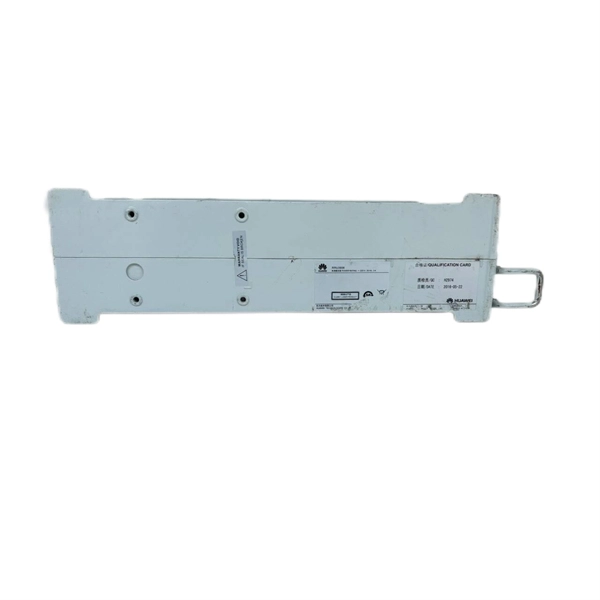
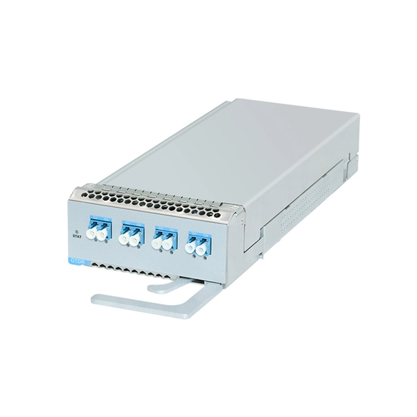
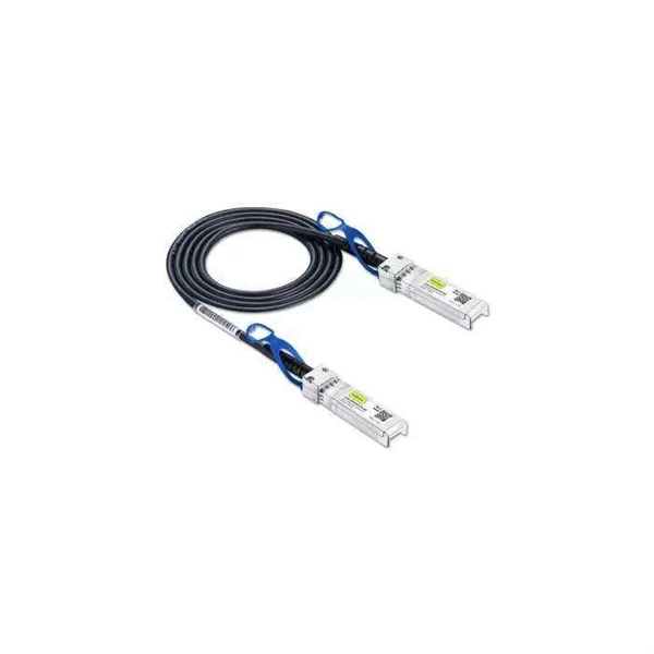
Introduction to the Internal Structure of the Optical Module
Optical module usually consists of a transmitter assembly (TOSA, containing a laser LD chip), a receiver assembly (ROSA, containing a photodetector PD chip), a driver circuit, an optoelectronic interface, a heat sink (some models), a housing, a pull ring and so on. The working principle of optical modules is illustrated in the diagram shown in the Optical Module Working Principle Diagram. Subsequently, the driver semiconductor laser. Optical modules are devices used to connect network devices, transmit and receive data between network devices, and can be used to convert optical and electrical signals. This article will introduce you to the. Laser (Light Source): Generally, a laser diode (LD) or light-emitting diode (LED) is used as the light source. LD is suitable for long-distance, high-speed transmission, while LED is used for short-distance, low-speed applications. It is the core device for connecting communication equipment with optical fibers. Modulator — encodes data onto the light.
[PDF Version]
-
Internal Structure of Data Center Racks
Rack frame: The structural skeleton that holds all mounted devices. Shelves and drawers: Used for non-rackmountable devices or. Crucial considerations include the types of IT racks for housing essential systems, the decision between preconfigured and customized solutions (given the tradeoffs among price, delivery times, and effort), and the choice between open and closed frame racks. Relevant factors include access. Data center racks are metal frames used for organizing IT equipment such as servers and switches. Selecting the right rack requires evaluating its height (U), depth, width, weight capacity, airflow design, power integration. Below, we outline four common slab types frequently considered in modern Data Center projects, along with their pros and cons: In this approach, a fully reinforced concrete slab is poured and cured on-site using traditional formwork. Regular. BIM | Data | AI | Helping Global Design Firms Scale with Dedicated BIM Documentation | Founder @ Au-mm | Architectural BIM Lead - Mission Critical Projects | Faculty When people outside the field hear "data center," they usually imagine a cold, dark room filled with servers blinking in sync.
[PDF Version]
-
Internal relays of relay protection devices
The fault can be located upstream or downstream of the relay's location, allowing appropriate protective devices to be operated inside or outside of the zone of protection.OverviewIn, a protective relay is a device designed to trip a when a is detected. The first protective relays were electromagnetic devices, relying on coils operating on moving par. Electromechanical protective relays operate by either, or. Unlike switching type electromechanical with fixed and usually ill-defined operating voltage thresholds. Electromechanical relays can be classified into several different types as follows: "Armature"-type relays have a pivoted lever supported on a hinge or knife-edge pivot, which carries a moving contact. These relays may.
-

Can the internal structure of a cable tray elbow be spliced
The NEC requirement for splicing cables and conductors installed in cable trays is stated in Sec. Splices are permitted in a cable tray if the splice is accessible and insulated. Cable Ladders use pre-fabricated fittings for when you need to change the ladders' direction or work around a site, as well as splices to join multiple lengths. All sizes of cable ladder are offered with a full range of fittings that allow you to bend, tee, cross, rise, or reduce the laying. With an innovative dove tail splice design, Eaton's B-Line series KwikSplice cable channel is designed to reduce complexity, improve versatility and speed installs. The most common cable tray connection methods include: Each method differs in installation time, cost, flexibility, and strength. Choosing the right one depends on project conditions, load. According to 392.
-
Internal Structure of Mobile Optical Cable
The simplest fiber optic cable is generally composed of four parts: core, cladding, coating, strength member, and jacket. The cladding is a thin layer that helps transmit data through the. An optical fiber cable is a complex structure designed to protect fragile glass fibers that transmit digital data using light signals. This advanced cabling solution allows fast, secure data transfer and telecom over long distances. This process is known as Total Internal Reflection (TIR).
-
Cable Tray Internal Wiring Method
NEC Article 392 explains cable trays, their components, appropriate wiring methods for cable trays, and instances where they are and are not permitted for use. It also focuses on construction and installation practices for cable trays. Here is the summary of the main points found. Hubbell Wiring Device-Kellems and Hubbell Premise Wiring are divisions of Hubbell Incorporated, a U. headquartered manufacturer with over 130 years of supplying solutions for the electrical and data markets. The Cable Tray ng standards, performance standards, test standards and application in this document have been tested extens ompetent professional en completely installed, without damage either to conductors or. The B-Line series Cable Tray Manual was produced by our technical staff. Cable trays give cables a clear path.
-
Cable tray internal wiring installation
Proper planning for installing cable tray includes calculations based on loading, support systems, cable/wire fill and spacing, conductor types, securing of the cables and wire, and proper grounding and bonding are all important aspects of cable tray installation. NEMA VE2 addresses cable tray installation and provides information on maintenance and system modification. The following pages address the 2014 National Electrical Code® requirements for cable tray systems as well as design solutions from practical experience. headquartered manufacturer with over 130 years of supplying solutions for the electrical and data markets. Hubbell's strength is demonstrated by a long-standing reputation for supplying reliable. en completely installed, without damage either to conductors or structural system use maintain spacing or to keep cables in place when the tray is ect the minimum bend ra-dius for cables as they exit the bottom of the cable tray. A rung spacing of 6 to 9 inches (150 to 230 mm) is preferable when. How about organizing your wiring with a cable tray system? Smart move.
[PDF Version]