-
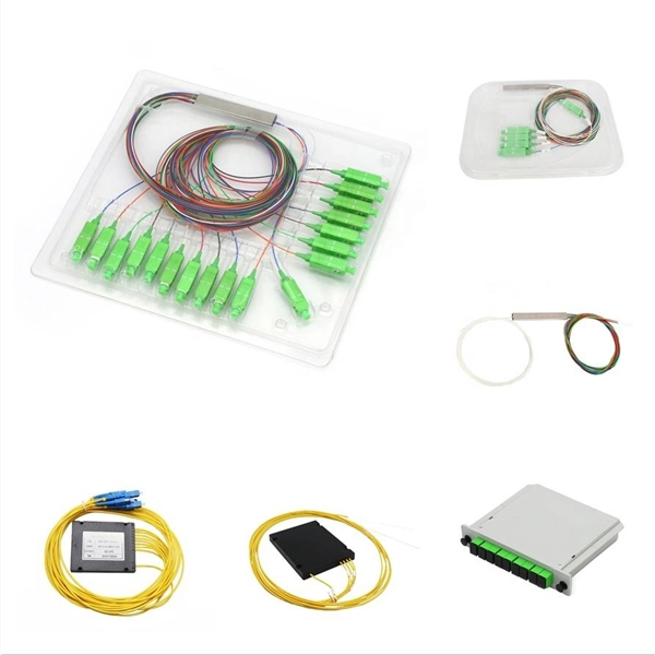
What can be installed on an ODF fiber optic patch panel
Modern high-density panels can support: 12 Ports: Small-scale or edge applications. An ODF is a centralized platform designed for terminating, cross-connecting, and managing optical fibers. It ensures fiber management is structured, minimizes signal loss, and provides accessibility for maintenance and future expansion. ODF Rack/Cabinet: Physical frame housing all terminations and. View our full range of Fiber Optic Patch Panels to browse available configurations, including Rack Mount, Wall Mount, and High-Density ODF solutions. A Fiber Optic Patch Panel, also known as an Optical Distribution Frame (ODF) or fiber termination enclosure, is a centralized hardware unit designed. This 2026 expert guide explains the functions, placement, structure, and application scenarios of ODFs and fiber patch panels-and includes a deep engineering FAQ that resolves real-world deployment challenges. The ODF System Components.
[PDF Version]
-
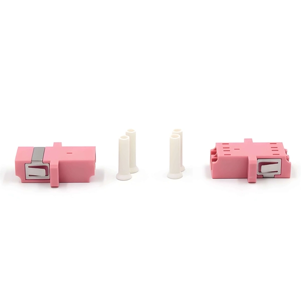
Odf fiber optic patch panel flange
An optical distribution frame(ODF) is a frame used to provide cable interconnections between communication facilities, which can integrate fiber splicing, fiber termination, fiber optic adapters &.
-
Latest Regulations on the Management of Optical Fiber Patch Cords
3‑E “Optical Fiber Cabling and Components Standard” was developed by the TIA TR‑42. Scope: This Standard specifies performance, transmission, and test and measurement requirements for premises optical fiber cable. For managing Passive Optical Networks (PON), the ITU-T G. Adopt smart labeling technologies like RFID, NFC, and digital tracking to speed up maintenance and reduce downtime. Keep detailed, up-to-date documentation and perform regular audits to. IEC Technical Committee (TC) 86—which prepares standards for fiber-optic systems, modules, devices and components—includes three main subcommittees: SC 86A (Fibers and Cables), SC 86B (Interconnecting Devices and Passive Components) and SC 86C (Systems and Active Devices). Most of the current. The Professional Association Of Fiber Optics www. (FOA) was founded in 1995 to help develop the workforce to build the fiber optic networks to support a rapid expansion in communications and the Internet. The charter of the FOA was to promote professionalism. Regulations and standards act as the backbone of fiber optic installations, ensuring that every step of the process meets stringent safety and performance criteria.
[PDF Version]
-
How to measure the optical attenuation value of fiber optic patch cords
The primary tool for measuring attenuation in installed fiber is an Optical Time Domain Reflectometer, or OTDR. The most fundamental parameter for optical fiber is geometry, since the dimensions of the fiber determine its ability to be spliced and terminated to other fibers. The core diameter, cladding diameter and concentricity are the most important factors on how well one can connect or splice two fibers. In this tutorial, we'll take a look at the.
-
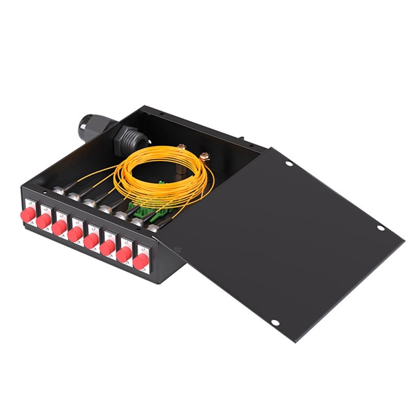
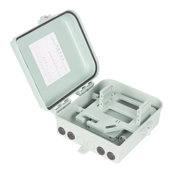
How does optical fiber enter ODF
Large multi-fiber cables are fed into the ODF and broken out into individual fibers or pigtails that are easier to manage. This complete guide explores everything you need to know about ODFs — from their structure, types, and key components, to installation best practices and modern design trends. Whether you're building a central office, data center, or FTTx distribution network, understanding the right ODF. An Optical Distribution Frame (ODF) is the central hub for fiber splicing, termination, patching, and cable protection in modern optical networks. They provide efficient fiber optic management, connectivity, and protection.
-
How to use a 96-core fiber optic patch panel
These high-density fiber patch panels allow a mix-and-match of e2XHD fiber and copper snap-in cassettes - up to 96 LC fibers or 48 copper ports per RU. Cassettes quickly snap in and pull out of the panel, making installation and changes easier than ever. These individual strands will then connect to electronic devices. This is precisely the problem the MPO/MTP® patch panel was designed to solve. Frankly, if you're deploying 40G, 100G, or higher, you can't afford to ignore this technology. The 96 Core Slide Drawer Patch Panel 1U UHD MPO/MTP-LC 4 Cassette is a versatile solution for high-density fiber management in data centers and telecom networks. Designed for 19″ rack-mount cabinets, it accommodates up to four HD MPO/MTP-LC cassettes, providing a plug-and-play system that. OptoSpan's WM-96 Wall Mount Termination and Splicing Enclosures provide a convenient, secure and organized housing for fiber optic connections and terminations, as well as a central point for splicing fiber optic cables for indoor or outdoor installations.
[PDF Version]
-
Does the fiber optic patch panel still need to be configured
Since proper installation is key for working with a fiber patch panel, step-by-step processes should be observed. Make sure there is sufficient room. The traditional fiber optic patch panel is no longer just a passive hardware box; it is a critical intersection point for managing cable geometry, mitigating insertion loss, and ensuring operational scalability. They enable efficient signal routing, maintenance, and troubleshooting within telecommunications and data center environments. Here's a step-by-step guide to help you properly arrange fiber optic patch panels in a data center.
-
What is a normal optical attenuation value for fiber optic patch cords
For single-mode fiber (the type used in long-distance and high-speed networks), typical values under normal conditions are about 0. Under ideal conditions, those numbers drop to around 0. Attenuation in fiber optics is the gradual loss of light signal strength as it travels through a fiber cable. For speeds up to 200M, the light attenuation must be less than -25dBm. With light attenuation at -27dBm, speeds are limited to a maximum of 100M. This calculator helps you estimate the total attenuation (signal loss) in a fiber optic cable link. This can be due to a variety of factors: scattering and absorption, intrinsic loss, extrinsic loss, bending losses and more. If you don't know what kind of losses to expect in your system, you won't know how many other components.