-
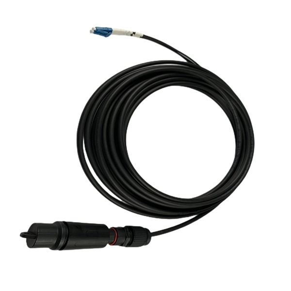
How to pull up a power fiber optic cable
Fiber optic cables should always be pulled by the strengthened yarn fibers inside the outer jacket. This article explores recommendations for pulling and installing fiber optic cable. Most fiber optic cables boast a pull strength of 100 – 200. Fiber optic cable is surprisingly strong, durable and pliable; however, several best practices should be followed to ensure a successful cable installation. Most fiber damage does not come from normal operation after the system is live. More than half of cable problems happen because of wrong pulling. In 2025, new tools like hydraulic blowers, smart monitors, and better grips help you lower risks, save money, and keep the. A duct is available from point A to point B, a pull tape is blown in, a fiber optic cable is attached to it and the cable is pulled through the duct.
-
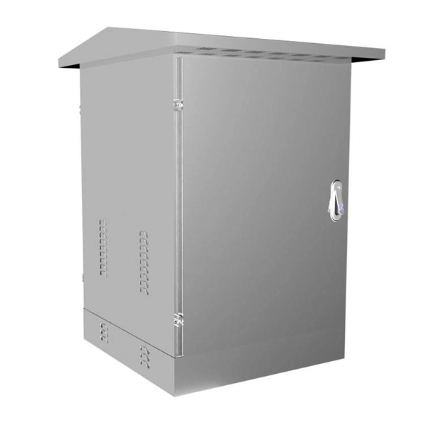
How to route large power cable trays
Learn how to install cable trays for large-scale projects with our professional, step-by-step guide covering industry standards, safety protocols, and efficient routing techniques. This guide covers the critical steps, from selecting the right electrical cable tray and performing accurate cable fill. Cable tray installation implies the construction of an electric road that will be safe. The beginning of success is to review the Bill of Quantities (BOQ) so that. Cable tray systems provide a safe, organized, and flexible method for supporting insulated conductors and cables in commercial and industrial electrical installations.
-
DC busbar power failure
If the busbar protection fails to trip when an external fault occurs or if it falsely trips while in use, the power system could become unstable. A total power outage will result from this. Regular dielectric testing is crucial to verify the quality of insulation and ensure that busbars can perform reliably under both normal. Busbar insulators are the backbone of electrical systems, ensuring safe power distribution by isolating conductors and preventing faults. However, harsh operating conditions, material degradation, and improper maintenance can lead to insulator failures—jeopardizing safety and system reliability. The DC-link capacitor selection is one of the first and most important steps. Consequently, power busing design needs critical consideration in terms of performance under converter operation, asymmetric loading, short-circuits, thermal and insulation breakdown.
[PDF Version]
-
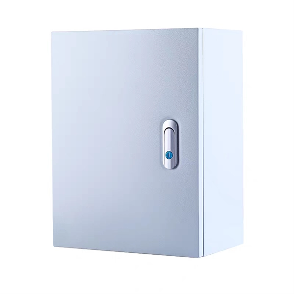
Construction site secondary power distribution box with 4 circuits
Electric power distribution systems are designed to serve their customers with reliable and high-quality power. The most common distribution system consists of simple radial circuits (feeders) that can be ov.
-
How to route fiber optic cables for high-voltage power lines
This technique takes a small, lightweight fiber optic cable and wraps it around or lashes it to the power line. The cable is called optical power attached cable (OPAC), and it is lashed to the power cable with a specialized tool that is pulled from the ground, such as a. Installing ADSS (All-Dielectric Self-Supporting) cables near live power lines demands precision, compliance with safety standards, and an understanding of high-voltage risks. This guide from GL FIBER breaks down the process into actionable steps, aligned with IEEE 524 and IEC 61935-1 protocols, to. Most aerial fiber optic cables are installed by lashing to a steel messenger wire strung between poles, but there is a category of cables with special high-strength jacket designs called all-dielectric self-supporting (ADSS) cables. ADSS cables are designed to withstand very high-tension loads. bles in a high voltage environment, with typical line voltages of 115 kV or more, requires the evaluation of certain critical parameters. Curr ntly, there are a limited number of industry documents that address the requirements for optical fiber cables near high voltage circuits.
[PDF Version]
-
Price of Power Grid Optical Cable Layout
As of recent market analysis, the price range for OPGW cables is generally between RMB 10,000 to RMB 30,000 per kilometer. OPGW Optical Ground Wire cables have become essential components in modern telecommunication and power distribution systems. This guide outlines typical cost ranges and the main drivers behind pricing to help formulate a budget and estimate expenses. Cost factors include material. development of communities. In economic terms, that means no unexpected costs due to on-site delays, professional project management. OPGW is primarily used by the electric utility industry, placed in the secure topmost position of the transmission line where it “shields” the all-important conductors from lightning while providing a telecommunications path for internal as well as third party communications. 52 per foot for wholesale bulk purchases, or $1 to $6 per foot at retail. Fiber optic construction is bringing high-speed internet connectivity to homes and businesses in.
[PDF Version]
-
How to determine light attenuation of red light using an optical power meter
Optical attenuation compares input and output power on a logarithmic scale. When powers are in linear units, the loss in decibels is: Attenuation (dB) = 10 × log10 (Pin / Pout) If the link length L is provided, the attenuation coefficient is: Coefficient (dB/km) =. Analyze optical power drop across fibers and links. Switch units, lengths, and calculation modes easily. Needed when attenuation is an. Optical power, required for measuring source power, receiver power and, when used with a test source, loss or attenuation, is the most important parameter and is required for almost every fiber optic test. Backscatter and wavelength measurements are the next most important and bandwidth or. Optical power meters are a key element in the optimization and maintenance of such optical networks and of their components. But, for designers, just starting to work in the fiber-optic design space, measuring attenuation can seem like a monumental task.
[PDF Version]
-
Can PoE power be turned off on a PoE switch
For TP-Link PoE switches, except for Unmanaged Switches, we can disable/enable PoE power on individual ports under PoE > PoE config, and PoE Status of PoE port is enabled by default settings. 08-27-2024 07:21 AM Just so we are confusing folks - We don't turn off switch port just to turn off PoE. To disable PoE only for an interface, go. Please note that the TL-SG108 doesn't support PoE at all. If a device does not need PoE the switch/UDM will not supply any power on that port. In the Network Operations app, select one of.
-
How to disconnect the power when installing a distribution box
To handle this safely, technicians must follow a strict lockout-tagout (LOTO) procedure. This ensures that no accidental reconnection occurs while the wires are being adjusted or inspected within the housing. Identify all power sources feeding the specific distribution blocks. The service disconnect rules, primarily outlined in NEC Article 230, Part VI, are fundamental to electrical safety, providing the means to de-energize an entire building from its power source. For a journeyman electrician or master electrician, a deep understanding of these regulations is. Before installation, it's important to know what makes up a distribution box. It has three categories: residential, commercial and industrial electrical distribution boxes, all of which play important roles in their respective electrical. Always shut off the power to an outlet before working on it—and then test with an electrical tester to be sure there's no voltage present. It is usually equipped with circuit breakers, fuses, terminal connectors, and other components.
[PDF Version]
-
Light collection power of the second-stage beam splitter
It is currently used in modern three-CCD cameras. An optically similar system is used in reverse as a beam-combiner in three- LCD projectors, in which light from three separate monochrome LCD displays is combined into a single full-color image for projection.OverviewA beam splitter or beamsplitter is an that splits a beam of into a transmitted and a reflected beam. It is a crucial part of many optical experimental and measurement systems, such as In its most common form, a cube, a beam splitter is made from two triangular glass which are glued together at their base using polyester,, or urethane-based adhesives. (Before these synthetic,. Beam splitters are sometimes used to recombine beams of light, as in a. In this case there are two incoming beams, and potentially two outgoing beams. But the amplitudes.
-
Can fiber optic cables be run alongside 35kV power cables
General Consideration: It is generally not recommended to run fiber optic cables in the same conduit as electrical power cables. This is due to several potential risks and complications that can arise from such an arrangement. When a communications cable runs parallel and in close proximity to a power cable, these magnetic fields induce unwanted currents—a phenomenon known as inductive coupling—into the sensitive data conductors. This induced noise can. TECHNICAL GUIDELINE July 30, 2020 TG030 Rev. Electrical Interference: Electrical cables can produce electromagnetic. Maintaining proper separation between power, data, and limited energy cabling is foundational to system performance, safety, and code compliance. Other than that you haven't provided much information, given. Laying network cables parallel to electrical cables is often necessary due to space constraints but comes with its own set of challenges, primarily due to electromagnetic interference (EMI).
[PDF Version]
-
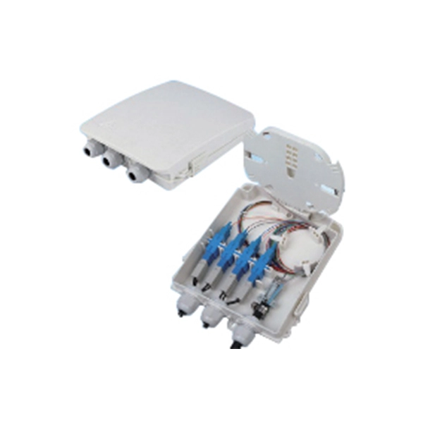
How are 36 cores of power optical fiber cable divided
Multi-core optical fiber is a breakthrough in optical networking that packs multiple cores into one fiber, enabling tremendous capacity gains via spatial division multiplexing. By carrying parallel channels in a single strand, MCF allows operators to multiply bandwidth without. These optical signals are transmitted (Tx) and received (Rx) at deliberate power levels expressed and measured in milliwatts (mW), an absolute optical power level. Absolute levels may also be represented as a relative optical power level, known decibel milliwatt or dBm. Its primary function is to split the optical signal of one input optical fiber into multiple optical signals and transmit them to. MTP/MPO cables are a class of high-density multi-core fiber optic connectivity solutions widely used in data centers and telecom networks, which are designed to achieve fast connection of multi-core fiber optics through a single interface. In contrast to conventional single-core fibers (one core on the fiber axis), MCF can have two or more.
[PDF Version]