-
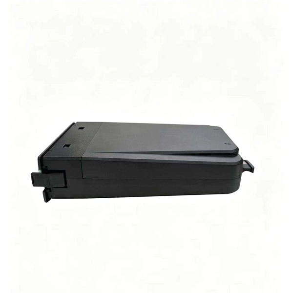
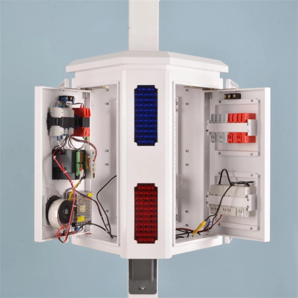
How to connect thick wire to the distribution box
Trim solid or stranded wire to length and insert into clamp-style terminals. Turn on the power and check your work. more Connecting wires of different thicknesses (gauges) can be. This guide provides step-by-step instructions for connecting a distribution box and highlights key factors to consider during installation. This connection method has a proprietary name in the distribution box-jumper. Proper assembly inside this box is paramount because a poorly made splice can generate excessive heat due to high resistance, creating. Below, I'll walk you through multiple ways to make basic wire connections in your home. It is usually equipped with circuit breakers, fuses, terminal connectors, and other components.
-
How to connect the cable tray ground wire
If an EGC cable is installed in or on a cable tray, it should be bonded to each or alternate cable tray sections via grounding clamps (this is not required by the NEC® but it is a desirable practice). Cable tray grounding wire is the safety connection that links your electrical system's cable tray to the ground. In addition to providing an electrical connection between the cable tray sections and the EGC, the. There are three wiring options for providing an EGC in a cable tray wiring system: An EGC conductor in or on the cable tray. Each multi-conductor cable with its individual EGC conductor.
-
How to learn how to wire a distribution box
In this video, we'll walk you through the process of wiring a home distribution box with a detailed connection diagram. more Welcome to our. Learn how to wire a distribution box step by step! This video shows real on-site footage of electrical installation, demonstrating safe and standardized wiring methods used by professionals. Covers wiring, placement, standards, and expert tips for a compliant setup.
-
How many bundles of wire are needed for the distribution box
A box fill calculator helps you determine how many wires and devices fit safely in your electrical box based on conductor size and box volume. This code is based upon the type of box, wires, wire sizes, wire clamps and conduit fittings. The distribution box is just one piece. Your power cables (included per project keywords) must handle the load too. Undersized wires cause: Cable Sizing Rule: For 20A circuits, use 12-gauge wire minimum. Tool Tip: Use calculators to check voltage. Although the pictures here are by far the most extreme box fill code violations, some common sense along with electrical code requirements limits the number of wires that can be put into an electrical box.
-
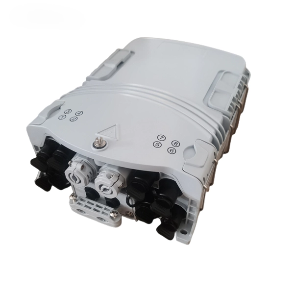
How to operate a fiber optic coupler
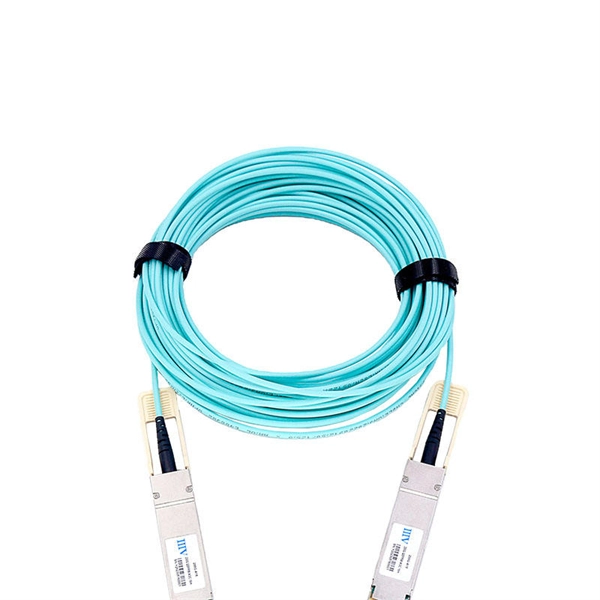
A fiber optic coupler splits or joins light signals. It helps you control how data moves in optical networks. Think about how many ports you need. Know the difference between passive and. Fiber optic adapters, also known as couplers, play a crucial role in fiber optic networks by providing a connection point between two fiber optic connectors. It enables optical signals to pass from one fiber to another with minimal loss, ensuring stable and reliable communication. In this article, we will discuss how to use fiber optic adapters, product selection, engineering. A fiber optic coupler is a device used to couple light from one or several input fibers into one or more fibers or from free space into the fiber. It is important to note that a fiber optic coupler has two different meanings: A fiber optic. Before you get the long distance, high speed and low latency fiber optic link for supply network in your system, you may encounter a situation that the length of a single roll fiber optic cable fails to meet your need, then you will need to con.
[PDF Version]
-
How much distance should the cable tray support be installed
Generally, standard trays require supports every 6 to 10 feet, while heavy-duty, long-span trays can handle distances of up to 20 feet between supports. To determine the proper spacing, consult the manufacturer's load capacity chart, which accounts for the total weight of the. The NEC requires that cable trays must be supported by members at an interval specified by the cable tray manufacturer, but not more than 5 feet for horizontal runs to support the weight of the cables and other loads. The NEC has a requirement for ladder-type cable trays. This spacing is crucial for adequate maintenance access, ease of inspection, and ensuring proper airflow for effective heat dissipation. Support Methods: Common support methods include trapeze hangers, which are. This is a description of how to select, install, and support these metal or plastic frames, on which electrical wires are installed.
[PDF Version]
-
How much does a 12-core fiber optic cable cost for smart buildings
00 per ft depending on terrain, access, and required precision for termination. Total ≈. Typical rates range from $0. Single-mode fiber costs less per foot than multimode fiber, but it requires more. This is a plenum rated distribution type fiber with a durable jacket which provides added protection during installation. Labor dominates the installed price. Here is the 2026 benchmark for cost of laying fiber optic cable per foot by method: Open trench (lawn/field): $0. Directional boring (road. VALUE Corning FREEDM® One 12-Strand Riser Fiber Optic Cable delivers premium performance, fast data speeds, and exceptional durability at a competitive price. Sold by the foot, this cable is customized to the exact length you need using our advanced cable-cutting machinery. In addition, multi-strand fiber cables also.
-
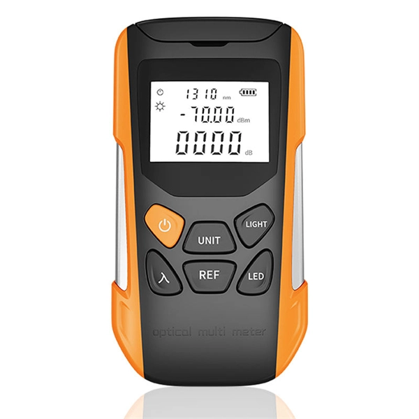
How to determine light attenuation of red light using an optical power meter
Optical attenuation compares input and output power on a logarithmic scale. When powers are in linear units, the loss in decibels is: Attenuation (dB) = 10 × log10 (Pin / Pout) If the link length L is provided, the attenuation coefficient is: Coefficient (dB/km) =. Analyze optical power drop across fibers and links. Switch units, lengths, and calculation modes easily. Needed when attenuation is an. Optical power, required for measuring source power, receiver power and, when used with a test source, loss or attenuation, is the most important parameter and is required for almost every fiber optic test. Backscatter and wavelength measurements are the next most important and bandwidth or. Optical power meters are a key element in the optimization and maintenance of such optical networks and of their components. But, for designers, just starting to work in the fiber-optic design space, measuring attenuation can seem like a monumental task.
[PDF Version]
-
How are 36 cores of power optical fiber cable divided
Multi-core optical fiber is a breakthrough in optical networking that packs multiple cores into one fiber, enabling tremendous capacity gains via spatial division multiplexing. By carrying parallel channels in a single strand, MCF allows operators to multiply bandwidth without. These optical signals are transmitted (Tx) and received (Rx) at deliberate power levels expressed and measured in milliwatts (mW), an absolute optical power level. Absolute levels may also be represented as a relative optical power level, known decibel milliwatt or dBm. Its primary function is to split the optical signal of one input optical fiber into multiple optical signals and transmit them to. MTP/MPO cables are a class of high-density multi-core fiber optic connectivity solutions widely used in data centers and telecom networks, which are designed to achieve fast connection of multi-core fiber optics through a single interface. In contrast to conventional single-core fibers (one core on the fiber axis), MCF can have two or more.
[PDF Version]