-
How to solve the problem of missing zeros in the electrical distribution box at the construction site
Quality inspection: Make sure the distribution box and its components meet the standards, check whether the wiring is firm, and whether the materials are qualified. Qualified Builders: Hire an experienced electrician for installation and connections to avoid mistakes and omissions. Learn how to install a distribution box safely and correctly. It takes the incoming power and safely distributes it to different circuits throughout your building. The good news is that most issues are easy to troubleshoot, especially if you follow the steps below. more 👉 DIY House wiring and maintenance handbook: https://selar.
-
How do fiberglass hard tails emit light
A comet tail is a projection of material from a that often becomes visible when illuminated by the, while the comet passes through the inner. As a comet approaches the Sun, causes the within the comet to and stream out of the, carrying dust away with them. Blown by the, these materials typically form two separate tails that extend outwards from th.
-
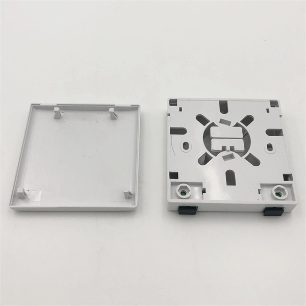
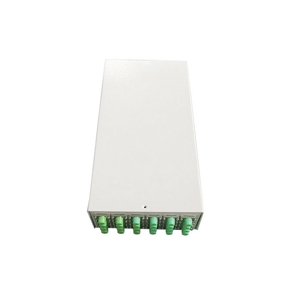
How to collect light inside the fiber distribution box
This paper describes the position-sensitive light-collection system that we use in our fast-beam laser experiments. The collection system consists of fiber-optic bundles whose facets are arranged to accept ligh.
-
Spacing of the side of the distribution box
Side clearance: There should be a minimum of 30 inches of clearance from the sides of all electrical equipment, but in no case less than the width of the equipment itself. This is referred to as the side-to-side working space. In industrial power distribution systems, cable distribution boxes (also known as power distributor boxes, distribution electrical boxes, or electrical power distribution boxes) are the core hub of power transmission, branching, and protection. Its layout directly affects the efficiency of the. NEC Article 314 establishes requirements for the installation and use of electrical boxes, conduit bodies, fittings, and handhole enclosures. NEC Article 408. Boxes distribute low currents in an area equipped with 1 to 12 RJ 45 sockets. They centralise connections to ensure flexibility and that the installation is up to date.
[PDF Version]
-
Should the cable management rack be installed in the front or the back
Leave space for cable management —especially in the back. Ensure front-to-back airflow by leaving gaps or using filler panels. This method helps maintain neatness and accessibility within the rack while ensuring efficient airflow and ease of maintenance. Both overhead and under floor pathways should be designed to support the weight of cables in the initial installation and it should also facilitate the addition of future cables. With proper design and structured tools, it helps organize cables, ensure stable signal transmission, simplify maintenance, and improve overall system. Here are some best practices for rack placement: Implementing hot and cold aisle containment is a fundamental strategy for improving airflow and cooling efficiency. The racks should be positioned in a way that optimizes.
-
How to determine light attenuation of red light using an optical power meter
Optical attenuation compares input and output power on a logarithmic scale. When powers are in linear units, the loss in decibels is: Attenuation (dB) = 10 × log10 (Pin / Pout) If the link length L is provided, the attenuation coefficient is: Coefficient (dB/km) =. Analyze optical power drop across fibers and links. Switch units, lengths, and calculation modes easily. Needed when attenuation is an. Optical power, required for measuring source power, receiver power and, when used with a test source, loss or attenuation, is the most important parameter and is required for almost every fiber optic test. Backscatter and wavelength measurements are the next most important and bandwidth or. Optical power meters are a key element in the optimization and maintenance of such optical networks and of their components. But, for designers, just starting to work in the fiber-optic design space, measuring attenuation can seem like a monumental task.
[PDF Version]
-
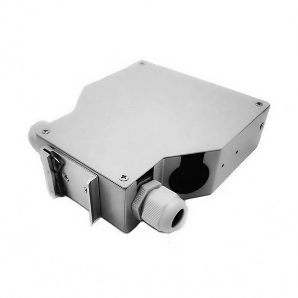
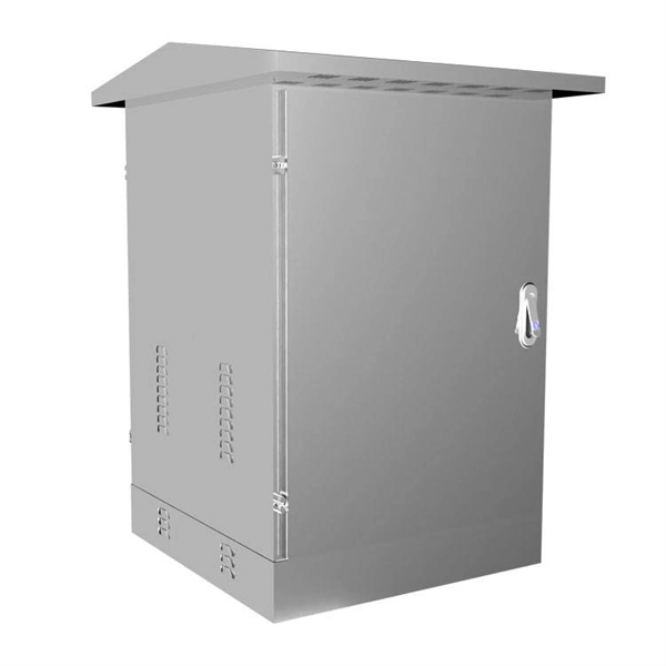
The power cable enters from the bottom of the distribution box
Cables can enter the structure from the floor (bottom entry) or from above (top entry. ) Distribution structures divide and send power to branch circuit protection devices and then to branch circuits to power downstream loads. Power. When installing a new overhead combination service for a residential service replacement we were told by the EI that we could not install our romex cables coming from under the house in a single 2" pipe approx. The scope of the article includes electrical requirements related to: Below is a complete overview. Once the box is securely in place, it's time to bring in the cables that will carry current from the main panel. Escape will cancel and close the window. Power from the utility company is typically delivered through three large conductors, which may enter the house overhead or underground. Overhead service. Fixed to a wall—This is a common approach for small electrical distribution boards. For bottom entry, the floor can incorporate a trench or false floor, which is often simpler since it provides.
[PDF Version]
-
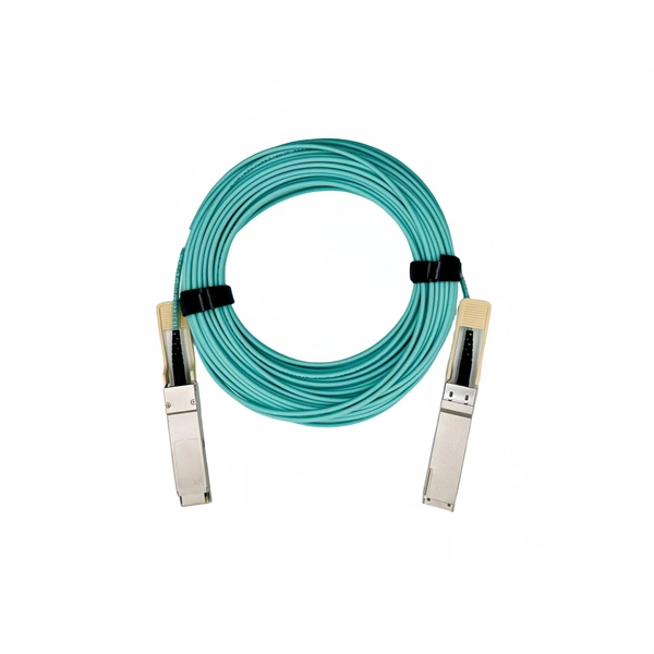
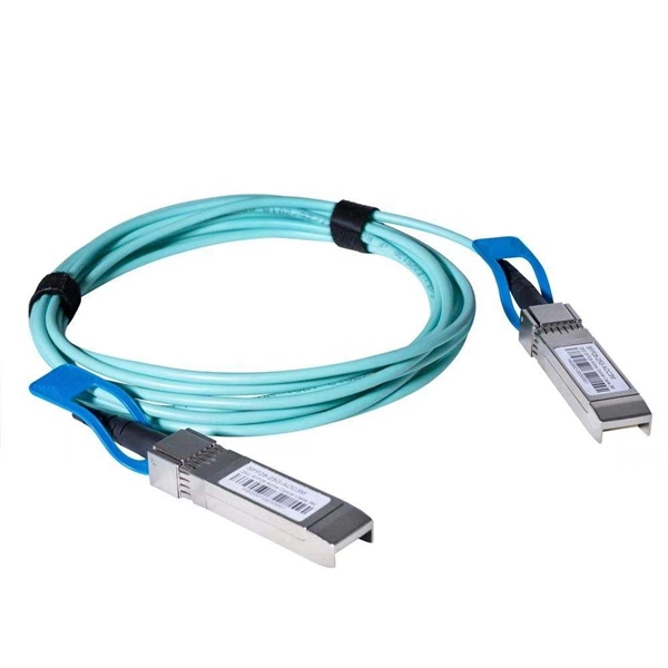
How is the serial interface of the XFP optical module
The XFP 2-wire serial interface is used for serial ID, digital diagnostics, and certain control functions. It was defined by an industry group in 2002, along with its interface to other electrical components, which is called XFI. XFP modules can be installed or replaced in an Extreme Networks switch, I/O module, or router without powering off the system. All Extreme Networks XFP modules comply with. This Juniper Networks® XFP-10G-S compatible XFP transceiver provides 10GBase-SR throughput up to 300m over multi-mode fiber (MMF) using a wavelength of 850nm via an LC connector. It can operate at temperatures between 0 and 70C. The transceiver is compliant with CPRI, eCPRI. With these features, this 10G SFP+. ID systems defined for the GBIC and SFP transceivers. 12 document apply to Beta-and Production-level units only. Physical Medium Dependent (PMD) sublayer and baseband medium, type 10GBASE-S (short wavelength serial), 10GBASE-L (long wavelength serial), and.
[PDF Version]
-
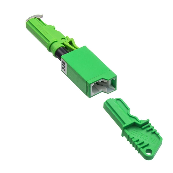
How to locate the fault point in a communication optical cable
Struggling to identify faults, validate polarity or ensure quality mechanical connector terminations in your fiber optic cables? Visual Fault Locators (VFLs) are a valuable tool that make troubleshooting fast and efficient. Let's dive into everything you need to know about mastering VFLs. Common Indicators of a Cable Break Signal Loss or Interruption: If data transmission is interrupted, it could indicate a break or severe bend. Physical. Finding a fiber fault typically involves the following steps: 1. However, physical damage can disrupt this infrastructure and cause significant network issues. When fiber cables sustain damage, specialized repair techniques help. To ensure the quality and continuity of fiber optic services, it is essential to identify and locate fiber optic cable faults as quickly and accurately as possible.