-
How to connect optical fiber cable to fiber optic pigtail
Make a precise cut for optimal splicing. Use an OTDR or power meter to ensure performance. Always use pre-tested, high-quality pigtails to reduce installation errors and improve network. Field-terminating connectors is a meticulous, high-pressure process where even a tiny mistake can force you to cut the fiber and start all over again. The most efficient way to terminate a. In this detailed video, we'll walk you through the fiber optic pigtail splicing process — from preparation to final testing. If you're new to fiber optics or want to enhance your technical skills, this guide will help you understand how to splice fiber pigtails safely and efficiently. --- 🔧 In. Executive Summary: A fiber optic pigtail is one of the most commonly specified yet least understood components in structured cabling.
-
How to peel fiber optic strands during pigtail splicing
Fiber Strippers: These are specialized tools designed to peel away the outer buffer and the microscopic coating of the fiber without scratching or nicking the glass core. High-Precision Cleaver: You cannot use scissors or standard snips for this. A fiber pigtail is a short length of optical fiber that comes with a high-quality, factory-polished connector already installed on one end, leaving a length of exposed glass on the other. Instead of building a connector from. Executive Summary: A fiber optic pigtail is one of the most commonly specified yet least understood components in structured cabling. Get the wrong connector type, the wrong polish, or skip proper fusion splicing technique—and you're looking at elevated signal loss, increased back reflection, and a. In this guide, you will find a chronological description of the fusion splicing process, the principal technical standards, and answers to the real-life questions network engineers and procurement teams may have. This post contains some basic knowledge of fiber optic pigtail, including pigtail connector types, fiber pigtail classifications, and fiber pigtail splicing methods.
[PDF Version]
-
How to connect a network cable to a pigtail
Connect the pigtail wire to the electrical outlet or end device by tightening it with a screw. But you have to loop the bare wire around the screw terminal first. This connection is. In this detailed video, we'll walk you through the fiber optic pigtail splicing process — from preparation to final testing. If you're new to fiber optics or want to enhance your technical skills, this guide will help you understand how to splice fiber pigtails safely and efficiently. This is exactly why most professional installers have moved away from field-termination and toward splicing. The National Electrical. Same as the optical jumper, when the connecting line is an optical cable (mostly indoor optical cable) and passes the standard test line, it is called an optical fiber pigtail. So, what is pigtail? How to wire pigtails? ZR Cable Pigtail What is pigtail Pigtail, also known as pigtail, has only one.
[PDF Version]
-
How to coil the pigtail together
After one end of the pigtail has been connected to your device, use lineman's pliers to twist together the bare end of the pigtail wires with the circuit wires, turning in a clockwise direction. A pigtail is composed of three strands of wire. Drunk posting ill conceived instructables since 2009. Here is a super-easy way permanently coil a cable such as a USB, Lightning, or similar data / charging cable. In this video, I demonstrate how to make a mechanically and electrically sound pigtail splice. When twisted properly, they maintain consistent power distribution while isolating faults. Imagine three wires needing to.
-
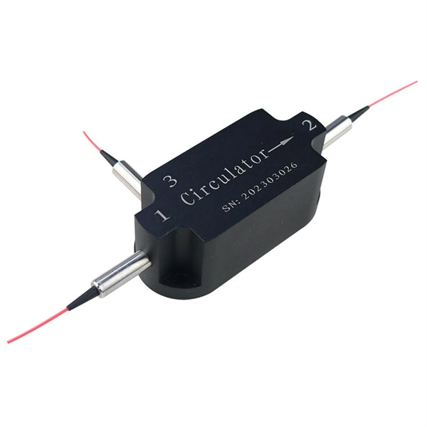
How to test the continuity of pigtail fiber
A visual fault locator (VFL) makes use of a visible spectrum laser light to test the continuity of the fiber and detect fault conditions. There are two reasons we may want to test bare fiber, by that we mean fiber that has not been terminated in connectors but is simply plain optical fiber, The first one is to ensure the fiber or cable being manufactured meets its specifications, as is done by every manufacturer. Fiber optic. The Optical Time Domain Reflectometer (OTDR) will be used to test splice loss and to conduct span analysis. An Optical Power Meter and Laser Light Source will be used to measure power loss on each completed ring or distribution span to verify continuity between fibers (no fibers incorrectly spliced. A visual check is often the first step when diagnosing a defective fiber pigtail. Continuity testing verifies that the fiber is intact and that light can pass through from one end to the other without any blockages. This comprehensive guide will equip you with the knowledge and skills to accurately assess the integrity of a pigtail, helping you identify issues.
[PDF Version]
-
How is the price of a fiber optic terminal box calculated
In conclusion, understanding the fiber termination box price involves several components, from the type and features to specific applications and advantages. When purchasing, consider not just the initial cos.
-
How to connect a contactor to a distribution box
First, find all the terminals on the contactor. Connect the line and load wires to the right terminals. Make sure. A contactor is an electromechanical switch that allows or interrupts the flow of electric current. It is widely used in applications such as motor control, lighting control, and power distribution. A contactor wiring diagram is a graphical representation of how contactors and other electrical. Properly wiring a contactor means connecting the control circuit to the coil terminals (A1/A2) and the high-voltage power circuit to the line (L1/L2/L3) and load (T1/T2/T3) terminals.
-
How to branch cables within a cable tray
Tees and Crosses: Create branches in the system to route cables to different areas. Reducers: Used to connect trays of different widths, often when moving from a main run (wide) to a branch run (narrow). Covers: Protect cables from falling debris, dust, moisture, and unauthorized. Let's take a closer look at the significance of managing cables in cable trays, the fundamental principles, methods, and steps required for effective implementation, as well as a case study of a successful cable management implementation. Managing cables in cable trays is not only essential for. This guide covers the critical steps, from selecting the right electrical cable tray and performing accurate cable fill calculations to managing a safe cable pull through and ensuring all bonding and grounding requirements are met. For licensed electricians, mastering these principles is essential. Installation of Cable in Cable Trays involves precise routing on support systems, NEC/IEC compliance, grounding, ampacity derating, bend radius control, segregation of services, fire safety, labeling, and reliable cable management for industrial and commercial facilities.
[PDF Version]