-
Is a laser diode made of fiber optic cable How do I connect it
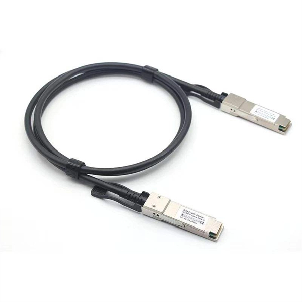
Fiber-coupled laser diodes are a type of laser system. Fiber-coupled. A fiber-coupled laser diode is a semiconductor device that generates coherent light, which is then focused and aligned precisely to be coupled into a fiber optic cable. The core principle involves using electrical current to stimulate the diode, creating photons through stimulated emission. This allows the laser light to be transmitted over long distances without losing too much power.
-
How to remove a loose pull ring from an optical module
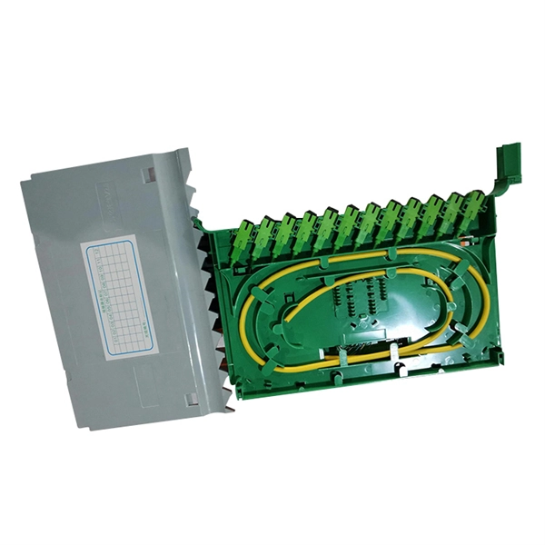
Gently pull the module latch or release ring, depending on the module design. To use an SFP optical module, first confirm that the host port is SFP-type. Figure 1 SFP Optical Module Installation. However, with the right approach and careful handling, you can safely remove a transceiver stuck in a switch without causing damage to your network equipment. There are two primary reasons why an SFP module might become stuck in a port: The SFP is wedged in the cage: This can occur due to slight. To connect an optical cable to an SFP module, use the appropriate patch cord (e. Once connected, verify that the port activity indicator is on and run diagnostic commands to check the module status. After removing the fiber jumper, insert a clean dust cover over it to protect the end face of the module.
-
How to cut materials for cable tray tees
The bends, tees, crosses, risers and reducers of wire mesh cable tray can be easily and quickly made live at the project by using a bolt cutter. Since the jaws of the bolt cutter drags a layer of zinc across the cut end and forms a protective layer. When a wire cable tray is cut, the fact that a. Cable trays are essential components in electrical installations, providing a safe and organized pathway for cables and wiring systems. more Developed by Interstates, this cable tray cutting guide acts as a guide. In the Oglaend System Cutting Guideline you can easily find out what the optimal cutting lengths/intervals are for all modular products. Following the advice given. This manual is designed to guide workers through the detailed production process of ladder cable trays, including the manufacture of horizontal elbows, tees, crosses, reducing bends, and vertical bends, with emphasis on precision, safety, and quality control. What's Involved in Producing Ladder.
[PDF Version]
-
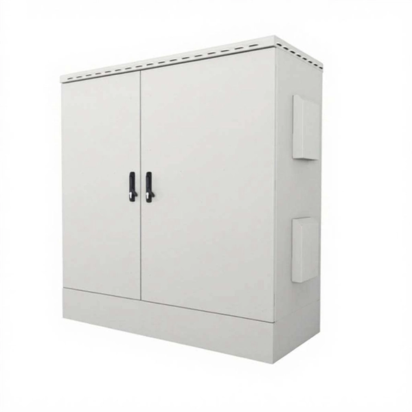
How to determine the installation method of a distribution box
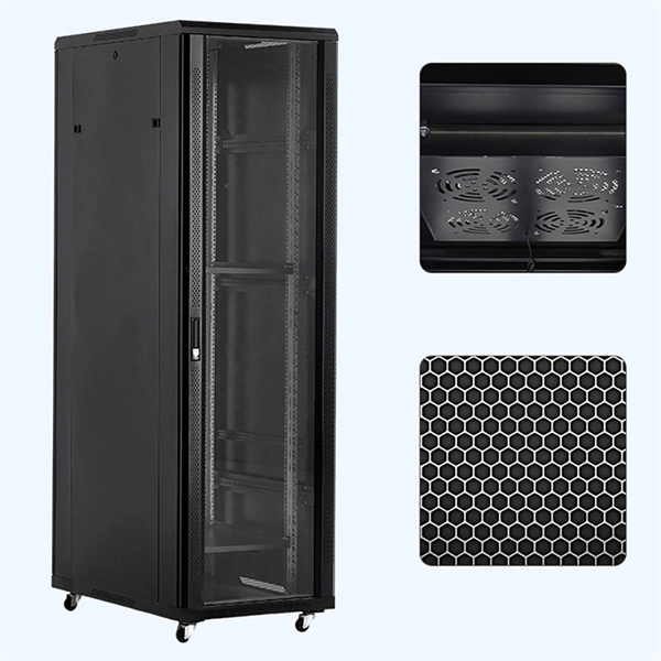
Choose the right box based on environment (indoor/outdoor), load capacity, and durability. Check for proper IP/NEMA ratings and material quality. In this guide, we'll break down everything you need to know to install a distribution box correctly and confidently. Ensure safe placement: install in. Whether you are an electrical contractor or a construction brigade, knowing how to properly and safely install distribution boxes is the basis of ensuring the safe operation of the entire system. Just like travelers need clear pathways and safety protocols, your electrical circuits need proper management to prevent chaos. The National Electrical Code (NEC) requirements might seem like bureaucratic. How to determine the size, installation method and wiring mode of distribution box? (1) Wiring method of distribution box 1) Generally, the incoming line of power distribution box adopts five wire system, that is, a, B and C three-way phase line (the general color is yellow, green and red), one way. This methodology document highlights the technical guidelines for the installation of Electrical Distribution Boards (DBs). Respective electrical rooms, LV.
[PDF Version]
-
How to connect a contactor to a distribution box
First, find all the terminals on the contactor. Connect the line and load wires to the right terminals. Make sure. A contactor is an electromechanical switch that allows or interrupts the flow of electric current. It is widely used in applications such as motor control, lighting control, and power distribution. A contactor wiring diagram is a graphical representation of how contactors and other electrical. Properly wiring a contactor means connecting the control circuit to the coil terminals (A1/A2) and the high-voltage power circuit to the line (L1/L2/L3) and load (T1/T2/T3) terminals.