-
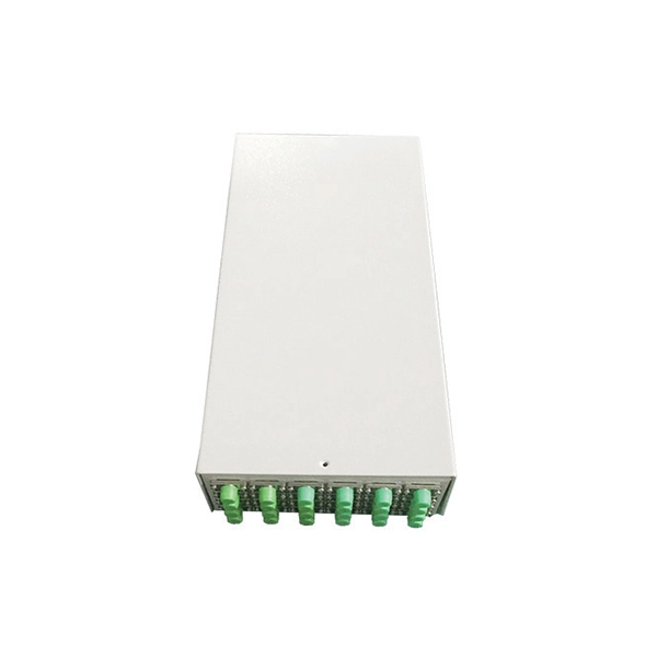
Should the cable management rack be installed in the front or the back
Leave space for cable management —especially in the back. Ensure front-to-back airflow by leaving gaps or using filler panels. This method helps maintain neatness and accessibility within the rack while ensuring efficient airflow and ease of maintenance. Both overhead and under floor pathways should be designed to support the weight of cables in the initial installation and it should also facilitate the addition of future cables. With proper design and structured tools, it helps organize cables, ensure stable signal transmission, simplify maintenance, and improve overall system. Here are some best practices for rack placement: Implementing hot and cold aisle containment is a fundamental strategy for improving airflow and cooling efficiency. The racks should be positioned in a way that optimizes.
-
How to determine the cable model in a cable tray
Choosing the right tray cable type — TC, TC-ER, VNTC, PLTC, or ITC — depends on the voltage class, environment, and NEC® article governing your installation. It is the standard wiring method for industrial plants, commercial buildings, and utility installations where cable trays provide accessible. Among the various cable types, tray cables are a preferred solution for robust, adaptable, code-compliant wiring. Whether you're an engineer, contractor, facilities manager or simply curious, this ultimate guide provides an in-depth understanding of tray cables, covering their types, standards. The cable jacket tells the story if you know how to read it. Manufacturers must print specific information on cable jackets per UL requirements, and understanding this code prevents most identification errors. The. Tray cable is a widely used type of multiconductor or multipair cable approved for installation in cable raceways and cable trays. In this technical guide, we'll explore all you.
[PDF Version]
-
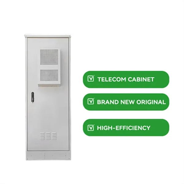
How to add a new IP segment to a core switch
The switch can have multiple IP addresses. Each IP address can be assigned to specified interfaces or ports, Link Aggregation Groups (LAGs), or Virtual Local Area Networks (VLANs). To remotely manage th.
-
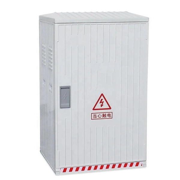
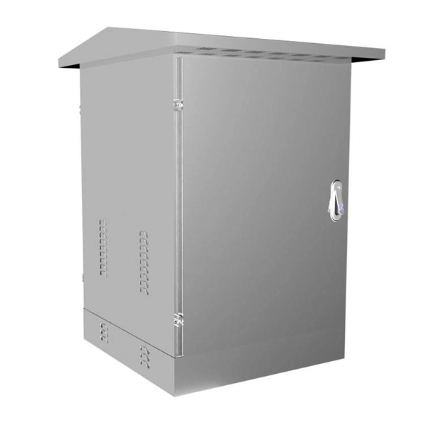
How to determine the installation method of a distribution box
Choose the right box based on environment (indoor/outdoor), load capacity, and durability. Check for proper IP/NEMA ratings and material quality. In this guide, we'll break down everything you need to know to install a distribution box correctly and confidently. Ensure safe placement: install in. Whether you are an electrical contractor or a construction brigade, knowing how to properly and safely install distribution boxes is the basis of ensuring the safe operation of the entire system. Just like travelers need clear pathways and safety protocols, your electrical circuits need proper management to prevent chaos. The National Electrical Code (NEC) requirements might seem like bureaucratic. How to determine the size, installation method and wiring mode of distribution box? (1) Wiring method of distribution box 1) Generally, the incoming line of power distribution box adopts five wire system, that is, a, B and C three-way phase line (the general color is yellow, green and red), one way. This methodology document highlights the technical guidelines for the installation of Electrical Distribution Boards (DBs). Respective electrical rooms, LV.
[PDF Version]
-
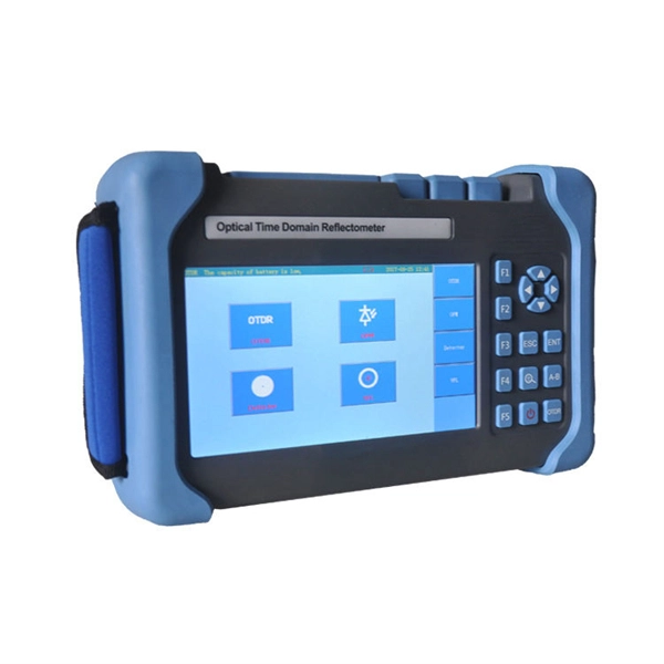
How to determine light attenuation of red light using an optical power meter
Optical attenuation compares input and output power on a logarithmic scale. When powers are in linear units, the loss in decibels is: Attenuation (dB) = 10 × log10 (Pin / Pout) If the link length L is provided, the attenuation coefficient is: Coefficient (dB/km) =. Analyze optical power drop across fibers and links. Switch units, lengths, and calculation modes easily. Needed when attenuation is an. Optical power, required for measuring source power, receiver power and, when used with a test source, loss or attenuation, is the most important parameter and is required for almost every fiber optic test. Backscatter and wavelength measurements are the next most important and bandwidth or. Optical power meters are a key element in the optimization and maintenance of such optical networks and of their components. But, for designers, just starting to work in the fiber-optic design space, measuring attenuation can seem like a monumental task.
[PDF Version]