-
How to fuse single-mode dual-core optical fibers
Learn how to splice fiber optic cable using fusion splicing with this complete step-by-step guide. Includes tools, best practices, loss standards (ITU-T G. 652), cost analysis, and FAQs for network engineers and installers. This article demonstrates the use of several fiber coupling efficiency analyses in OpticStudio. This article demonstrates how to set up a coupling system. Thorlabs offers a varied selection of single mode (SM), polarization-maintaining (PM), multimode (MM), and double-clad fiber couplers, as well as 1x8 and 1x16 SM PLC splitters; 1x4, 1x8, and 1x16 PM PLC splitters; wideband multimode circulators; RGB combiners; and WDMs. Single-mode fibers allow only a single mode of light to propagate through the core, resulting in less signal dispersion and higher bandwidth capabilities. Regardless of the type of fiber network you're deploying, be it for telecom, enterprise data centers, or smart city infrastructure, fusion splicing provides the benefits of. Fused couplers are used to split optical signals between two fibers, or to combine optical signals from two fibers into one fiber. 2-core o In optical modules, "core".
[PDF Version]
-
How much optical loss does a fiber optic cold connector typically experience
Generally, for single-mode connectors, the recommended insertion loss is below 0. Insertion loss, also known as attenuation, is the loss of optical power that occurs when light passes through a fiber optic connector. It is caused by factors such as misalignment, air gaps, and imperfections in the connector components. This article explores various connector types—such as SC, LC, FC, ST, APC, and UPC—and analyzes how their design and polishing affect IL and RL performance. Insertion Loss (IL): Measures the. Fiber loss, also called fiber optic attenuation or attenuation loss, refers to the loss of signal between input and output.
-
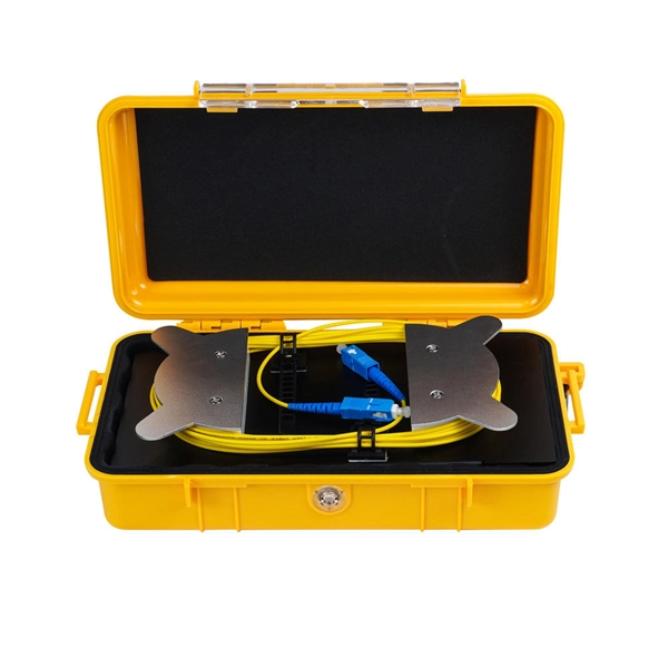
How to strip the outer layer of a 72-core optical cable
FOS03 Fiber strippers remove the coating from the fiber optic cable to expose the glass fiber. Above is a diagram showing the various layers of a typical indoor patch cable. Other types of cables may have different construction or additional layers, but regardless of the number and types of layers involved, the following generally holds true. Before any splicing can occur, whether it's mechanical or fusion. In this lesson, we will identify and examine cables, then prepare them for splicing or termintion by stripping the cable to expose the coated fibers.
-
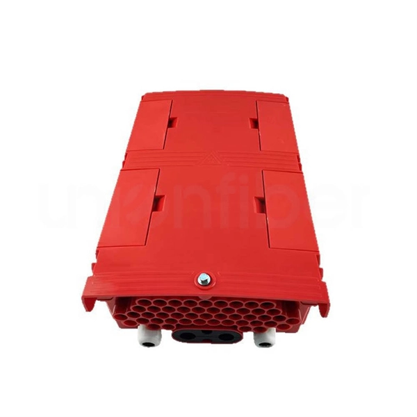
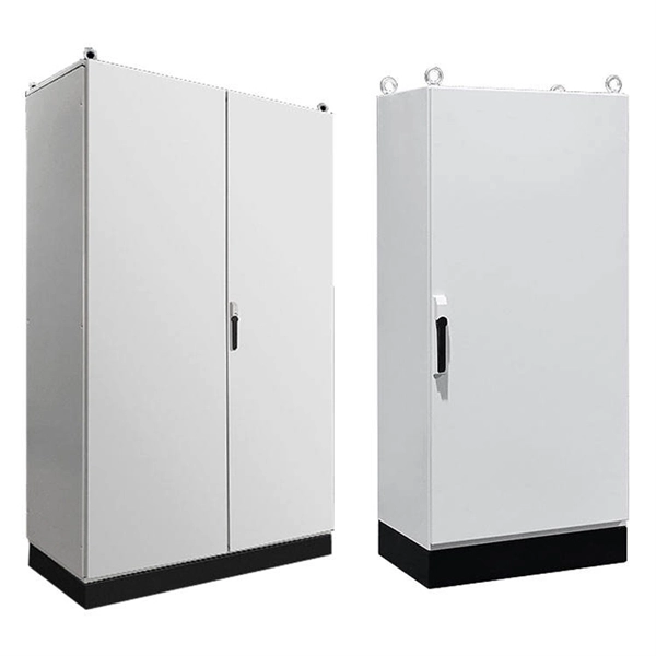
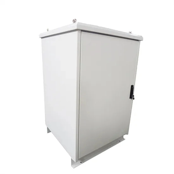
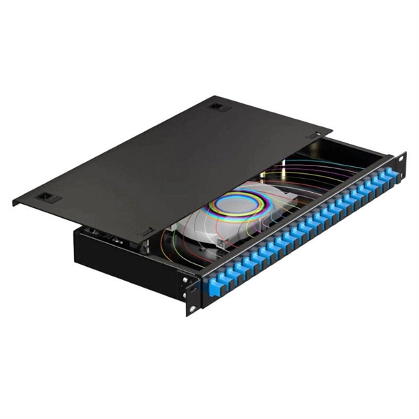
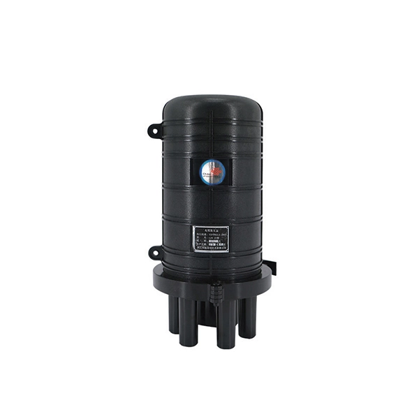
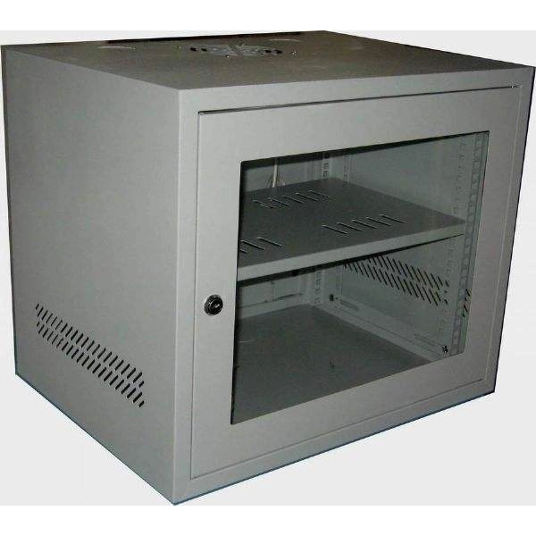
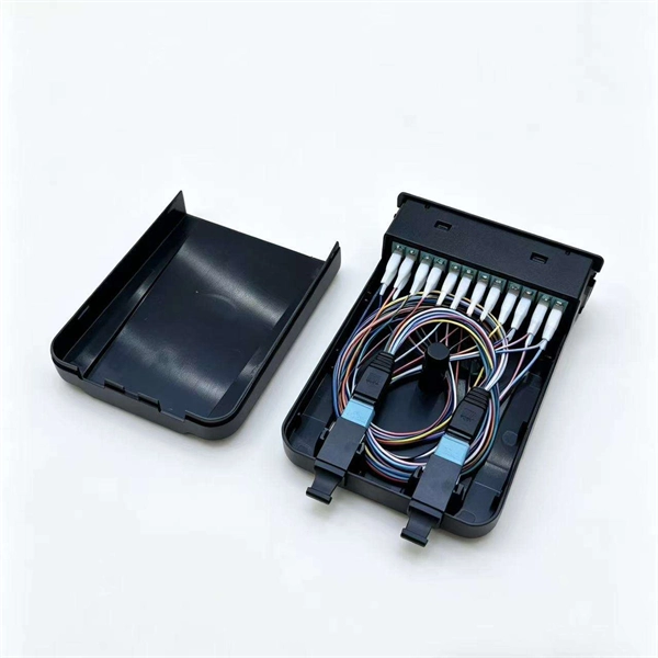
How many optical fibers can a fiber optic terminal box support at most
FTB max for mass deployment in residential units – terminates 168 fibers in a compact design. The HTB8048 Fiber Optic Terminal Box is a versatile, high-capacity termination solution for FTTx applications, offering secure fiber splicing, distribution, and cable management. The FTB product family offers modularity and ease of installation supporting multiple application options, significantly. This guide explains how to evaluate fiber termination box capacity correctly, including fiber count, port configuration, splitter accommodation, and future growth. Many buyers assume “capacity” simply means the number of adapter ports on the front panel (for example, 8 ports or 16 ports).
-
How many optical modules are in one rack
While the industry-standard OSFP (Octal Small Form-Factor Pluggable) module has successfully enabled 400Gbps, 800Gbps, and 1. 6Tbps optical pluggable modules , it is limited to 32 modules per Rack Unit (RU), typically requiring 2 RUs to achieve 102. 8Tbps of switching. The actual number of optical modules used primarily depends on the following factors. 6T QSFP-DD or OSFP modules, provide: In short: each NVIDIA GPU node needs multiple optical links to achieve optimized throughput in AI supercomputers. So, how many optical modules does a data center typically need? In this post, we will explore the usage of optical modules in traditional three-tier, improved. In the market, there are different versions of the ratio of optical transceivers to the number of GPUs, and the figures of various versions are not consistent mainly because the amount of optical modules required under different networking architectures is not the same. As CPO is increasingly used, concerns about reliability and manufacturability will be addressed, and as bandwidth keeps going up, CPO will take over all scale-up connections over the next few.
[PDF Version]
-
How to fix the ribbon optical cable distribution box
Fixing a ribbon cable typically involves identifying the damaged section, carefully stripping the insulation to expose the conductors, and then either soldering a replacement wire or using a specialized crimping tool to attach a new connector; the specific method depends on the. Fixing a ribbon cable typically involves identifying the damaged section, carefully stripping the insulation to expose the conductors, and then either soldering a replacement wire or using a specialized crimping tool to attach a new connector; the specific method depends on the. This article serves as a comprehensive guide to troubleshooting and repairing ribbon cables, providing step-by-step instructions and tips to help you fix these delicate components and ensure the optimal functioning of your devices. Ribbon cables, also known as flat cables or multi-wire planar. Repairing damaged ribbon cables might seem daunting, but with the right knowledge and tools, it's possible to restore functionality and save costs. By the end of this post, you'll have the confidence and know-how to tackle this common electronic repair issue on your own.
[PDF Version]
-
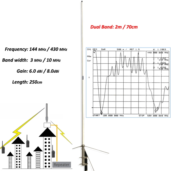
How to connect RRU optical modules in series
A fiber optic cable connects the RRU to the RBS main unit or an expanded macro RBS. The RRUs can be connected in a cascade configuration and a star configuration with optical cable links. User Guide About This Document About This Document Purpose This document describes the RRU hardware and provides instructions in hardware installation, cable connections, hardware installation check, and hardware maintenance. It also provides checklists as reference. In this document, eRRU3232 is used as an example. When wrapping the waterproofing tape, apply even force to extend the tape until the width of the tape is 1/2 of the original width. Start-up Below you will find brief information for RRU RFD01F Series.
-
How to convert an electrical port to an optical port on a switch
A switch SFP port converts electrical signals into optical signals via SFP transceivers, or maintains them electrically for copper connections. By using an SFP to RJ45 adapter (e. 5G SFP), you can seamlessly connect legacy Ethernet devices to modern fiber-optic. The RJ45 port is a built-in electrical port of a Gigabit Ethernet switch, and it is mainly connected by Category 5, Category 5e, Category 6, and Category 6e twisted-pair cables. However, modern networks often combine both technologies. The good news: you can bridge them easily using the right hardware, such as media. An SFP port on a switch or router SFP port enables network engineers to connect multiple media types, from fiber optic links to copper Ethernet. An SFP transceiver acts as a compact, hot-swappable optical transceiver that.
-
How to connect the traction rope for optical fiber communication cables
Use a swivel pulling eye to connect the pull rope to the cable to prevent pulling tension causing twisting forces on the cable. When the ground conditions are complex (such as rivers, trees, etc. The belt is then driven by a. In fact, there are two methods for aerial optical cables laying: one is "fixed-pulley traction method", including "manual traction method" and "mechanical traction method"; the other is "cable tray moving and releasing method". Outdoor cable may be direct buried, pulled or blown into conduit or innerduct, or installed aerially between poles.
-
How to remove the 10G optical module
To safely remove an SFP module, follow these steps: Disable the port in your network device settings or power off the device to avoid electrical damage. Gently pull the module latch or release ring, depending on the module design. To prevent damage to a transceiver and to any connected cables, disconnect all cables before installing or removing a module. There is no need to. Before installing an SFP or SFP+ module, we need to know some caution tips first.
-
451 How much does it cost to lay optical cable per kilometer according to quota
Total: $60,000-$120,000 per km. Assumptions: modest urban fringe, typical permits. The price range typically reflects trenching, ducting, cable, and right‑of‑way work, plus labor and equipment. Cost ranges reflect urban. Roadside Telecommunications (RS-TC) Fiber Optic Cable Installation Adjusted Capital Cost Scatter Plot The data used to produce this cost plot are sourced from the ITS Sample Unit Costs Database. These cost data are obtained directly from a variety of sources.
-
How to remove the optical module after it s been inserted
Gently pull the module latch or release ring, depending on the module design. Disconnect the optical cable. If significant resistance is felt, stop, remove the module, recheck the orientation, and inspect the port. After removing the fiber jumper, insert a clean dust cover over it to protect the end face of the module. You should hear the latching mechanism clicks while it is firmly seated.