-
Directional drilling hits fiber optic cable
Directional boring is a trenchless method of installing dark fiber optic cable underground along a predetermined bore path. Here's how it typically works: Planning: The process starts with careful planning, including surveying. The horizontal directional drilling (HDD) industry is at the forefront of the ongoing fiber optic revolution in the United States. With dark fiber optic line. According to the National Telecommunications and Information Administration (NTIA), the Infrastructure Investment and Jobs Act (IIJA) passed by Congress commits $65 billion toward broadband expansion. NTIA established the Broadband Equity, Access and Deployment (BEAD) Program to manage $42. 25. Insurance coverage cannot be bound or changed via submission of any online form/application provided on this site or otherwise, e-mail, voice mail or facsimile.
-
What is a horizontal optical cable junction box called
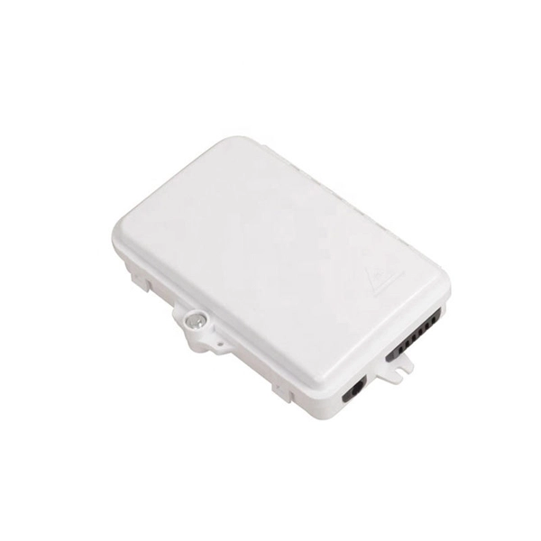
Fiber Cable Joint Box is a device used to provide space and protection for fiber optic cables spliced together. Optical cable splice boxes protect the splicing parts of optical fibers from various hazards, such as water seepage due to adverse. A Fiber Terminal Box (FTB) is a customer-side termination and distribution device used at the end of the optical network. ■ What Is a Fiber. Fiber optic splice closures are essential components in today's communication networks. These closures protect and organize splicingfiber connections, ensuring the integrity of opticalsignal transmission.
-
Cable tray horizontal tee cutting method
Completely adaptable, B-Line Flextray is designed to accommodate jobsite changes. For the best results, use a WB30BC Angular Blade Offset Bolt Cutter . to produce a clean cut. Do not use center cut style cutters, as they will leave a rough, burred cut that can damage cables and/o oximately a 45° angle. Cut the bottom wires firs in the order as shown. Flip the tray. To properly bond Hubbell ® painted cable tray, remove the plastic masking device from the trays on each end (exposing the pre-galvanized wire), and splice sections together using Hubbell ® splice kits. For cable trays that are not UL Classified as being “Suitable as an Equipment Grounding. Horizontal Tees link three 10" straight channel sections or compatible transitional fittings, enabling the creation of a sleek and efficient horizontal branch within a fiber routing system. Item code: HT Reducing Tee: W1>W2. Only two splices are required to securely connect tray widths of wire basket tray. The. Use this guide to learn the most effective installation practices when installing Cablofil tray. Engineers and contractors in North America and around the world have found.
[PDF Version]
-
Drilling holes for positioning cable tray fixing brackets
Drill the M10 hole at the flat surface of the cable tray and fasten it by M10 x 25 pan head bolt. Structural building members should never be cut, and cable trays should not be installed in hoist way or where subject to physical. Welcome to Engineerings. The following tools are commonly used for installation of cable tray: Marking of Cable Tray using a square that reaches across the width of the cable tray, gauge off the edge of one side rail and mark both flanges.
-
Dangers in drilling cable tray hangers
Your original article already highlights the biggest dangers: contact with energized cables, overheating caused by overload, structural collapse, sharp edges, debris buildup, fire spread, and grounding failure. Recognize electrical cable tray misuse that can lead to electric shock and arc-flash/blast events and fires caused by overheating. The use and installation of cable trays is covered by legally enforceable OSHA regulations in 29 CFR 1910. If a tray is overloaded, corroded, poorly supported, or contains live cables, it can create severe risks for workers and equipment. Cable trays are available in a variety of configurations and must be properly. Most of the electrical engineers show their curiosity in getting experience on cable tray installations service or task. Most of engineers take it as a mechanical formation to be taken care of it. 305(a)(3) and within various provisions of the National Electric Code (NEC). This manual will offer practical engineering knowledge.
[PDF Version]
-
Construction Scheme for Horizontal Cable Trays
The National Electrical Code (NEC) is the ultimate authority for any cable tray installation. Specifically, NEC Article 392 governs the use, installation, and construction specifications for these systems. Hubbell Wiring Device-Kellems and Hubbell Premise Wiring are divisions of Hubbell Incorporated, a U. headquartered manufacturer with over 130 years of supplying solutions for the electrical and data markets. Hubbell's strength is demonstrated by a long-standing reputation for supplying reliable. A printable 2-page reference card sent to your inbox. Need to renew your Electrician license? Pick your state and browse state-approved Electrician CE courses — complete your continuing education hours online, with instant reporting. Source Limitations: Obtain cable tray components through one source from a single manufacturer.
-
Horizontal deviation of each meter of horizontal cable tray
Horizontal deviation: ≤2mm per meter. Must be level, plumb, and securely mounted on supports. Calculate horizontal, vertical, or compound cable tray offsets based on bend angle, offset distance, and available installation space. Use dedicated splice plates and. The maximum horizontal distance shall be 76-meters (250 ft). For ease of cable installation and future expansion in hallway or major distribution routes, cable trays are the preferred method for distributing the horizontal wiring from the telecommunications room to the communication outlets. When. NEMA Standards Publication VE 2-2018 Cable Tray Installation Guidelines Endorsed by Cable Tray Institute www. com Published by: National Electrical Manufacturers Association 1300 North 17th Street, Suite 900 Rosslyn, Virginia 22209 www. This spacing should generally be no less than 0. The primary reason for this separation is to minimize electromagnetic interference (EMI), which could.
[PDF Version]