-
Extinction Ratio of Fiber Optic Sensors
In the world of fiber optics, the extinction ratio is a critical yet often overlooked parameter that can make or break signal integrity. This article explains what extinction ratio is, why it matters for reducing bit error rates in optical communication, and how it impacts optical module. Comprehensive Guide to Polarization Extinction Ratio in Fiber Optic Sensor s Introduction to Polarization Extinction Ratio The polarization extinction ratio (PER) is a critical parameter in fiber optic sensors that measures the degree of polarization extinction between two orthogonal polarization. Extinction ratio measurement at the connector level can quickly reveal alignment issues. The polarization axes of both fibers must be aligned before fusion. A poorly aligned splice is one of the most common sources of PER loss in. Cross coupling in regards to a birefringent fiber, quantified by extinction ratio, indicates the amount of light which is able to mix between the two polarization axes. To overcome this limitation, we propose and demonstrate a novel resonator design with an intrinsically high polarization.
[PDF Version]
-
What is the extinction ratio of an optical transmitter
Extinction ratio, when used to describe the performance of an optical transmitter used in digital communications, is simply the ratio of the energy (power) used to transmit a logic level '1', to the energy used to transmit a logic level '0'. Although specifications are defined by industry standards and test method-ologies loosely described, historically it has been. P1 and P0 are represented by (binary 1) and (binary 0) respectively. ♦ What is the Extinction Ratio (ER)? Extinction Ratio (ER) is the ratio of the optical power when the. The Extinction Ratio (ER) is a fundamental metric for evaluating the performance of systems designed to switch between distinct high-power and low-power states. Please consult the ST297-2015 for information on all SDI optical signal parameters.
-
How to pull up a power fiber optic cable
Fiber optic cables should always be pulled by the strengthened yarn fibers inside the outer jacket. This article explores recommendations for pulling and installing fiber optic cable. Most fiber optic cables boast a pull strength of 100 – 200. Fiber optic cable is surprisingly strong, durable and pliable; however, several best practices should be followed to ensure a successful cable installation. Most fiber damage does not come from normal operation after the system is live. More than half of cable problems happen because of wrong pulling. In 2025, new tools like hydraulic blowers, smart monitors, and better grips help you lower risks, save money, and keep the. A duct is available from point A to point B, a pull tape is blown in, a fiber optic cable is attached to it and the cable is pulled through the duct.
-
How are optical power meters classified
An optical power meter (OPM) is a device used to measure the power in an signal. The term usually refers to a device for testing average power in systems. Other general purpose light power measuring devices are usually called,, power meters (can be sensors or ), or lux meters. A typical optical power meter consists of a , measuring and display. The sens.
-
Light collection power of the second-stage beam splitter
It is currently used in modern three-CCD cameras. An optically similar system is used in reverse as a beam-combiner in three- LCD projectors, in which light from three separate monochrome LCD displays is combined into a single full-color image for projection.OverviewA beam splitter or beamsplitter is an that splits a beam of into a transmitted and a reflected beam. It is a crucial part of many optical experimental and measurement systems, such as In its most common form, a cube, a beam splitter is made from two triangular glass which are glued together at their base using polyester,, or urethane-based adhesives. (Before these synthetic,. Beam splitters are sometimes used to recombine beams of light, as in a. In this case there are two incoming beams, and potentially two outgoing beams. But the amplitudes.
-
DC busbar power failure
If the busbar protection fails to trip when an external fault occurs or if it falsely trips while in use, the power system could become unstable. A total power outage will result from this. Regular dielectric testing is crucial to verify the quality of insulation and ensure that busbars can perform reliably under both normal. Busbar insulators are the backbone of electrical systems, ensuring safe power distribution by isolating conductors and preventing faults. However, harsh operating conditions, material degradation, and improper maintenance can lead to insulator failures—jeopardizing safety and system reliability. The DC-link capacitor selection is one of the first and most important steps. Consequently, power busing design needs critical consideration in terms of performance under converter operation, asymmetric loading, short-circuits, thermal and insulation breakdown.
[PDF Version]
-
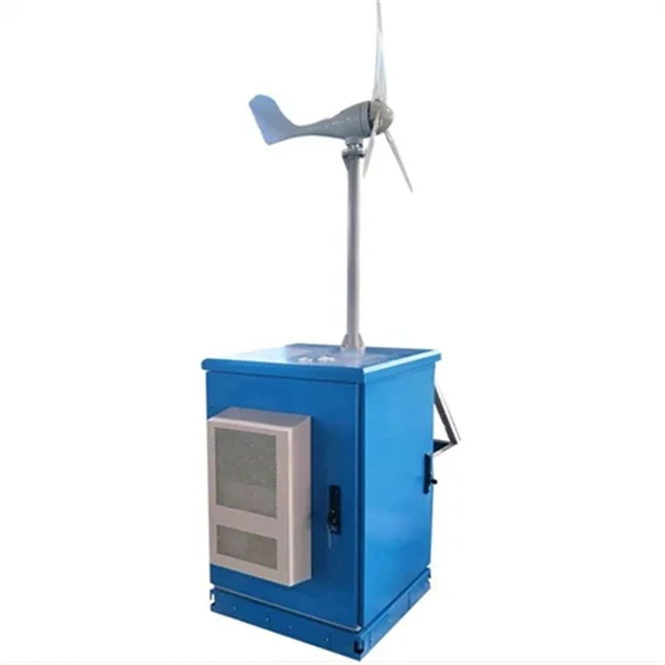
Anti-residual power systems for wind power generation
A hybrid wind-solar energy system consists of the following components: 1. Solar panels 2. Wind turbine – see our guide to the best wind turbines 3. Charge controller 4. Battery bank 5. Inverter 6. Power dis.
-
How to use a red light power meter
Lets say you are a light therapy enthusiast that wants to take your own proper measurements. Or you bought a red light therapy product and want to verify it meets outputs the intensity that it claimed. Then.
-
Function of the small busbar in the central power switch
The bus bar is a metal strip that distributes electrical current to the individual circuit breakers. In most assemblies you will find horizontal main bars, vertical risers, neutral and equipment-ground buses, and purpose-designed. What are Busbars, Bus Stabs, Circuit Spaces, Breaker Slots, Neutral Terminals, and Ground Terminals in an Electrical Panel or Load Center? Electric panels and load centers in residential and commercial applications have some different setting for breaker installation ad load circuit distribution. They connect directly to the main power source and are designed to handle high current loads safely. Circuit Breakers act as protective devices within the panel.