-
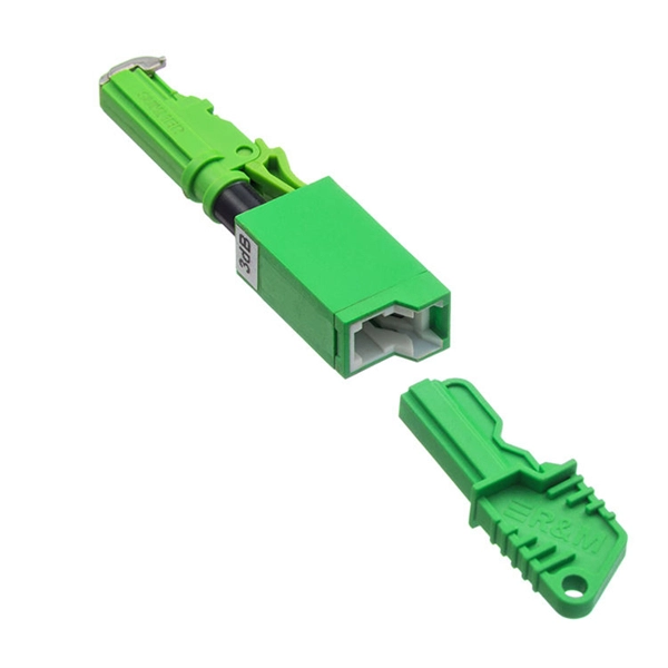
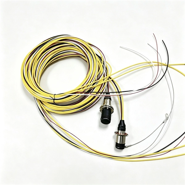
Unpacking of Drop Cable
A drop cable is the final segment of the telecommunications network that physically connects a service provider's infrastructure to a customer's property. This cable runs from a point on the utility network (such as a pole, pedestal, or vault) directly to the side of a home or. A drop cable, commonly referred to as a cable drop, is a critical component in network connectivity, typically used to connect a computer's Network Interface Card (NIC) to a wall plate. WARNING: Unrestrained cable ends may cause injury to your eyes or body and can damage the cable fitting, or fibers if suddenly released from a coil. A cable drop, also known as a last-mile cable, connects the main distribution network to individual end-users, bridging the gap. Recognizing that no two networks are alike, Clearfield has developed the industry's widest choice of drop cable solutions – speeding deployments and providing the flexibility of configuration that best suits your network environment, network design and drop cable needs.
[PDF Version]
-
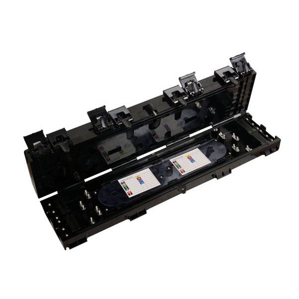
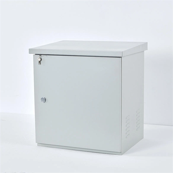
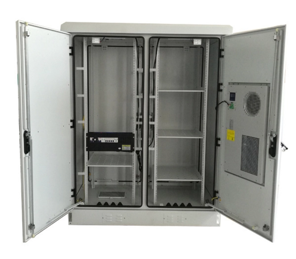
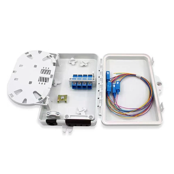
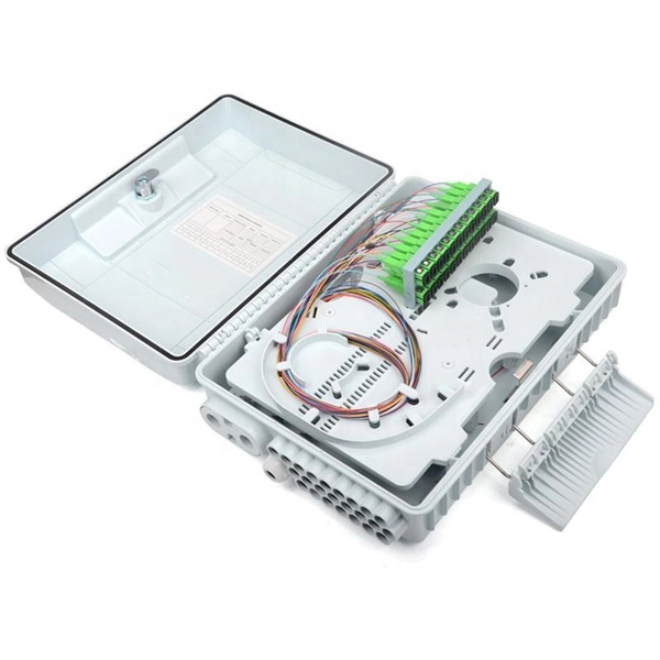
Telecom Fiber Optic Cable Drop Box
A Fiber Optic Termination Box is designed to secure and organize fiber optic connections, typically by linking fiber cables to an optical device through a patch cable. It can also function as a fiber optic distribu.
-
How to pull up a power fiber optic cable
Fiber optic cables should always be pulled by the strengthened yarn fibers inside the outer jacket. This article explores recommendations for pulling and installing fiber optic cable. Most fiber optic cables boast a pull strength of 100 – 200. Fiber optic cable is surprisingly strong, durable and pliable; however, several best practices should be followed to ensure a successful cable installation. Most fiber damage does not come from normal operation after the system is live. More than half of cable problems happen because of wrong pulling. In 2025, new tools like hydraulic blowers, smart monitors, and better grips help you lower risks, save money, and keep the. A duct is available from point A to point B, a pull tape is blown in, a fiber optic cable is attached to it and the cable is pulled through the duct.
-
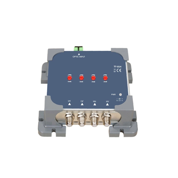
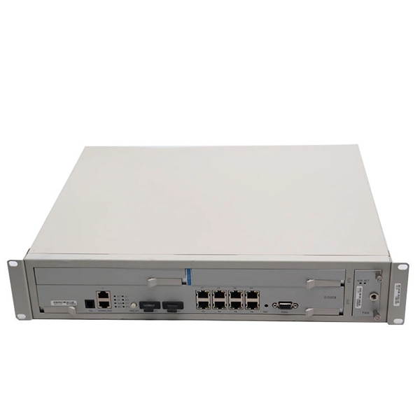
Fiber optic cable connected to router then connected to switch
If using a network switch with SFP ports, insert the fiber optic transceiver into the SFP port and connect the fiber optic cable to the transceiver. Connect the other end of the Ethernet cable to your network device, such as a computer, router, or. Fiber Optic Transceiver: Often used with media converters or network switches, these devices convert electrical signals to optical signals and vice versa. Patch Panel. As we speak I just have optic fibre (Community Fibre) connected to my Huawei modem / Linksys Velop which will be connected to a new POE switch (need to identify the best model to be compatible with my optic fibre extension project). Network topology refers to the way in which the links and nodes of a network are arranged in relation to each other. Use a standard Ethernet cable (Cat5e/Cat6) to.
[PDF Version]
-
Single-mode port connected to multimode fiber optic cable
Single mode and multimode fiber cables are quite different when it comes to size, light source, signal, and so on. So, they definitely are not interchangeable, and compatibility issues can occur when you try to connect a single mode fiber optic connector to a multimode network. This is where fiber conversion comes in. Single-mode. To realize the short-range direct connection to the end B switch with the same port, the same 10GBASE-SR SFP+ module should be plugged into the end B switch port. What if end B is located in. It's possible because Multi-mode optical cables have a very wide fiber core – 62. Understanding the key differences between these two technologies is essential for IT professionals, business owners, and even homeowners looking to future-proof their network.
-
Translate the cable tray by 45 degrees
To create a 45-degree bend, cut the side rails to remove a segment calculated by the formula (Tan (22. Google's service, offered free of charge, instantly translates words, phrases, and web pages between English and over 100 other languages. So basically from my middle line what size to mark either side to cut my lip away to create different angles. Calculate horizontal, vertical, or compound cable tray offsets based on bend angle, offset distance, and available installation space. Measure this distance along the straight tray. ADVANCED S PRODUCTS I ASP 45° inuous system as well as stand-alone elements. 5∘ cuts on two separate pieces of cable tray. The second piece's cut must be in the opposite direction. Easy step to make 45 degree offset cable tray/Pipe and Air duct Cable tray 90 Degree Bend ! Cable tray ( Hindi) Cable tray 22. Distance of 145 mm ×.
[PDF Version]
-
Cable tray connector installation price
Cable tray pricing depends on materials, coatings, size, supplier margins, and order quantity —plus hidden costs like shipping and installation. Cable tray installation cost per meter varies by specifications; GangLong Fiberglass offers kits for raised floor system and facility needs. This guide breaks down everything buyers need to know, from price trends to cost-saving tips. The average cable tray price per meter ranges from $2 to. A cable tray system is used to support insulated electrical cables used for power distribution, control, and communication. A 2026 Comparison vs. The majority of individuals will consider the cost of the components. That number matters, but it's rarely the one that decides whether a project stays within budget. The real cost shows up later, during installation, during upgrades, and during the first few years of operation.
[PDF Version]
-
Installation of galvanized plastic cable trays
This guide covers the critical steps, from selecting the right electrical cable tray and performing accurate cable fill calculations to managing a safe cable pull through and ensuring all bonding and grounding requirements are met. Are you looking for a cost-effective and durable solution for organizing and protecting your cables? Look no further than cable tray galvanized. But before you lay the first tray or clamp down a single cable, you need a solid plan. This guide breaks down the process step by step. The selection of material and finish is a function of the environment in wh tant in a wide range of environments, and easily formable (Appendices II and III). The process described here takes a systematic approach to ensuring that cable tray installations meet safety, reliability, and project-specific needs while following to. Method Statement installation of Cable Trays and Ladders - Planning Engineer FZE.
[PDF Version]
-
Manufacturing of Trapezoidal Cable Tray Elbows
Professional Cable Tray Elbow Making | Metal Fabrication Tutorial Learn how to make cable tray elbows professionally with step-by-step guidance. Whether you are a DIY enthusiast. Search by Cooperative Patent Classifications (CPCs): These are commonly used to represent ideas in place of keywords, and can also be entered in a search term box. If you're searching for seat belts, you could also search for B60R22/00 to retrieve documents that mention safety belts or body. Cable trays and fittings from Selco Manufacturing offer distinct advantages for various applications. The following are some key benefits and considerations to guide your selection process. There are several essential benefits of using cable trays from Selco Manufacturing, including: Better. This manual is designed to guide workers through the detailed production process of ladder cable trays, including the manufacture of horizontal elbows, tees, crosses, reducing bends, and vertical bends, with emphasis on precision, safety, and quality control.
[PDF Version]
-
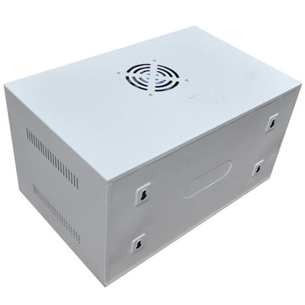
Benin Optical Cable Blowing Machine
A cable blowing machine (also known as a fiber blowing machine) is a machine designed to fit cables into telecommunication ducts and with the use of compressed air or water.
-
OPGW optical cable manufacturer in Lebanon
APAR designs and manufactures OPGW cables using advanced stranding technology, precision fiber integration processes, and stringent quality control systems. is a leading telecommunication company and a leading provider of telephony systems, networking, security and CCTV systems, Home Automation Systems, and Nurse Call System. IMATEL was founded in 1986 as a telecommunication provider. OptiLink was built on a simple belief: world-class fiber infrastructure shouldn't be reserved for the largest enterprises. This comprehensive analysis profiles the Top 10. Optical fiber composite overhead ground wire (OPGW) 1. Installed at the top of high-voltage and extra-high-voltage transmission lines, OPGW cables provide lightning. OPGW is primarily used by the electric utility industry, placed in the secure topmost position of the transmission line where it “shields” the all-important conductors from lightning while providing a telecommunications path for internal as well as third party communications.
[PDF Version]
-
How to install the cable tray beam bend
The fittings can fastened to the cable tray rail either with double clamps of type DOP A2 or with truss-head bolts of type FRS and combination nuts. The exceptions to this are vertical bends, adjustable bend elements and fittings with a side height of 35 mm. These fittings can only be screwed on. Beam bracket PK1 is attached to the lower flange of an I beam. These guidelines are not intended to cover all details or variations in cable ladder and cable tray. en completely installed, without damage either to conductors or structural system use maintain spacing or to keep cables in place when the tray is ect the minimum bend ra-dius for cables as they exit the bottom of the cable tray. A rung spacing of 6 to 9 inches (150 to 230 mm) is preferable when. Hubbell's NEXTFRAME® Ladder Tray is the effective and widely used cable runway that supports and delivers bundles of cable between cabinets, racks, and closets, along walls, and suspended from ceilings. Cable ladder systems and cable tray systems shall be manufactured in accordance with BS EN 61537, channel support.
[PDF Version]