-
How to test the continuity of a multimode fiber optic cable
The three standard methods for testing fiber optic cabling are a visible light source, power meter and light source, and optical time domain reflectometer (OTDR). Fiber optic testing for continuity is crucial in ensuring that light transmits through fiber optic cables without interruptions, safeguarding seamless data transmission. As the components like fiber, connectors, splices, LED or laser sources, detectors and receivers are being developed, testing confirms their performance specifications and helps. Fiber optic testing ensures the performance and reliability of fiber optic networks. It helps minimize downtime, reduce maintenance costs, and support system upgrades or reconfigurations. If it's a long outside plant cable with intermediate splices, you will probably want to verify the individual splices with an OTDR also, since that's the only way to make.
[PDF Version]
-
Fiber optic cable test chart to check for broken ends
Use a Fiber Inspection Microscope – 200–400× magnification reveals scratches or pits on ferrule end-face. Visual Fault Locator (VFL) – Injects a red laser (650 nm); light leakage indicates bend, crack, or break. The process of testing any fiber optic cable plant during and after installation includes all the procedures covered so far. As network speeds and bandwidth demands increase, fiber performance requirements have become more stringent. Corning recommends that all fiber optic systems be tested to a minimum set. Here are the most common fiber optic testing methods used by network professionals: Conducting a visual inspection test involves using a fiber scope or microscope to examine the endfaces of connectors for dirt, scratches, or cracks. Cable contamination can also.
-
How to connect the fiber optic test patch cord
Just use the one-jumper reference method to set the reference and an adapter to connect the jumper to the test reference cord. You can put in a fibre patch cord at home. You just need to follow easy steps and be careful. Unfortunately, equipment cords are also. Correct patch-cord installation is essential for maintaining low insertion loss, stable return loss, and long-term reliability in both indoor and outdoor fiber networks. This guide addresses expert-certified best practices applied by professionals in the telecommunications, data. Watch as we demonstrate the testing process for 12-fiber MPO patch cords using a laser source. more Watch. In today's high-performance networks, fiber optic patch cables are the lifelines that ensure smooth data flow across switches, servers, and routers. Even the most advanced optical transceivers can only perform at their peak when paired with properly installed, clean, and precisely managed fiber.
[PDF Version]
-
Manufacturer of Single Fiber Optic Distribution Cabinets
Get custom solutions: Our trained and skilled engineering team can create variations of our fiber optic cabinets based on the size, scale and scope of the enclosure that you need.
-
Fiber Optic Cable Tension Load Test Standard
This Applications Engineering Note (AEN 135) explains and recommends standard measurement methods for characterizing optical fiber system performance. FOA procedures, such as OFSTP-7 (single-mode) and OFSTP-14 (multimode), align with TIA and IEC standards. They describe how to set a '0 dB' reference, control mode power distribution, and use proper wavelengths. These procedures ensure you get consistent, repeatable results that meet international. d suppliers of electrical construction services. We're here to support your fiber network needs.
-
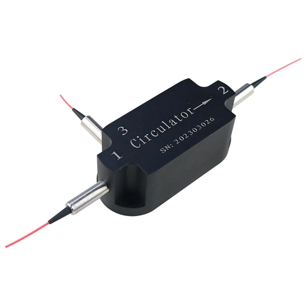
How to test the continuity of pigtail fiber
A visual fault locator (VFL) makes use of a visible spectrum laser light to test the continuity of the fiber and detect fault conditions. There are two reasons we may want to test bare fiber, by that we mean fiber that has not been terminated in connectors but is simply plain optical fiber, The first one is to ensure the fiber or cable being manufactured meets its specifications, as is done by every manufacturer. Fiber optic. The Optical Time Domain Reflectometer (OTDR) will be used to test splice loss and to conduct span analysis. An Optical Power Meter and Laser Light Source will be used to measure power loss on each completed ring or distribution span to verify continuity between fibers (no fibers incorrectly spliced. A visual check is often the first step when diagnosing a defective fiber pigtail. Continuity testing verifies that the fiber is intact and that light can pass through from one end to the other without any blockages. This comprehensive guide will equip you with the knowledge and skills to accurately assess the integrity of a pigtail, helping you identify issues.
[PDF Version]
-
How to connect the power supply to a fiber optic switch
We'll show you how to connect power and network using a fiber optic cable linked to the core switch in the control room. No extra adapters needed—just plug directly into an AC outlet. This setup is perfect for extending your network to outdoor IP cameras or remote locations. more Learn. Fiber connectivity to the power supply will pass through a standards-based SFP (small form-factor pluggable) interface which allows operators to communicate with the power supply using their chosen vendor solution. The opportunities and efficiencies they offer speak for themselves—but, as they spread to locations both indoors and out, you're probably feeling the crunch caused by not having enough. While in this post, we mainly focus on the PoE system that using fiber optic with power to solve unusual applications specifically in real life, which may need to achieve greater distance, higher bandwidth, or better reliability. Concerns go from laying. CONFIGURING THE SWITCH IN DESIGO CC/CERBERUS DMS.
[PDF Version]
-
Fiber optic cable T-knot fixing
Trim off any frayed or damaged ends of the cable. Strip the plastic coating off of the cut ends until you have enough wire exposed to fit into a metal terminal. Crip the terminals using a fiber optic crimper. Dekam Fiber's state-of-the-art solutions, including our UltraRepair kits, make these processes accessible and reliable. Let's explore how to keep your networks running smoothly in 2025 and beyond. Construction Activities: Accidental damage during construction. I cut my ATT fiber optic internet cable. However, physical damage can disrupt this infrastructure and cause significant network issues.
-
Can a static fiber optic cable be connected to a router
You can't directly connect a fiber optic cable to your router. You need an intermediary device. This comprehensive guide combines industry standards with field-tested practices to ensure you achieve a rock-solid. To connect your fiber optic cable to a router, ensure you have the following: Fiber optic modem (ONT): Most fiber connections require an Optical Network Terminal (ONT), provided by your ISP. The fiber line terminates at the Optical Network Terminal (ONT), which is typically supplied and installed by the internet service provider.
-
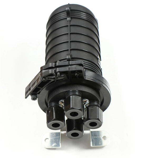
How many optical fibers can a fiber optic terminal box connect to
It integrates a splice tray, pre-terminated drop cables (1, 2, 4, or 8 fibers), fiber patch cords, and shutter-type adapters in one compact enclosure. An Access Terminal Box (ATB), also known as a fiber access socket or fiber pizza box, is an indoor optical connection device used to link fiber drop cables with the optical distribution network (ODN). Built with an IP65-rated enclosure, this terminal box is designed to withstand harsh environments, making it suitable. FTB max for mass deployment in residential units – terminates 168 fibers in a compact design.
-
Are ODF fiber optic cables typically placed in data centers
ODFs are typically installed in data centres, telecommunication hubs and central offices. It serves for fiber optic splicing, termination, storage of excess fibers, and protection. It organizes fiber connectors, patch. An Optical Distribution Frame is a specially designed enclosure used to manage, organise, connect and protect fibre optic cables. With the rise of high-density data centers and FTTH systems, traditional ODF designs are being complemented by MPO/MTP-based fiber patch panels.