-
A Comprehensive Guide to Seismic Supports for Palestinian Bridge Structures
Hatem Alwahsh f• Dynamic analysis: the analysis shall be based on an appropriate ground motion representation and shall be performed using accepted principles of dynamics. The main methods of dyn.
-
Comprehensive Cable Tray Layout
Download a comprehensive set of Cable Tray Installation CAD Blocks in DWG format, ideal for electrical engineers, MEP designers, and industrial layout planners. Hubbell Wiring Device-Kellems and Hubbell Premise Wiring are divisions of Hubbell Incorporated, a U. Hubbell's strength is demonstrated by a long-standing reputation for supplying reliable. Cable tray (or cable ladder) systems are a popular alternative to electrical conduit systems, as they have an outstanding record for dependable service, design flexibility and cost savings in commercial and industrial applications. The Cable Tray ng standards, performance standards, test standards and application in this document have been tested extens ompetent professional en completely installed, without damage either to conductors or. At its heart, Cable Tray Design, Layout means choosing and setting up cable trays to hold and protect electrical and data cables. Cable trays give cables a clear path. This collection includes installation details for ladder trays, perforated trays, solid-bottom trays, and wire mesh trays, along with.
[PDF Version]
-
Price of pigtail box manufacturing process
IMARC Group's report titled “Corrugated Box Manufacturing Plant Project Report 2024: Industry Trends, Plant Setup, Machinery, Raw Materials, Investment Opportunities, Cost and Revenue”provides a co.
-
Manufacturing Process of Mesh Cable Tray End Plates
Watch how precision welding and automation technology transform raw materials into high-quality, durable cable tray mesh. 🔹 Key steps: ✔ Linear feeding – insert the straight line into the feeding trolley and feed it into the welding system controlled by the servo motor; ✔. Wire mesh cable trays are widely used in modern electrical wiring systems due to their open structure, excellent ventilation, and ease of installation. Compared to ladder or solid-bottom trays, they are more flexible and better suited for complex environments. more This video will show the complete process of manufacturing. Cable tray manufacturing relies on a coordinated production line of specialized machines: a roll forming line shapes the profile, a CNC press brake handles secondary bending, a punch press creates mounting holes and ventilation slots, and a shearing line cuts the finished tray to length. Together. Finally, surface treatment, such as powder coating or hot-dip galvanizing, provides corrosion protection and a finished look.
[PDF Version]
-
Cable tray dip coating process
Steel trays get dipped in very hot molten zinc (around 450°C). The zinc bonds tightly to the steel, creating a thick, tough layer. Process: Degreasing → Pickling → Rinsing → Fluxing → Drying → Hot-dip galvanizing → Cooling → Passivation (optional) → Inspection. Hot-dip galvanizing is a process that enhances the durability of cable trays by creating a protective zinc coating, safeguarding them from corrosion. It is cost-effective, protects against a wide variety of environmental chemicals, and is self-healing if an area becomes unprotected through cuts or scratches. Steel is coated with zinc through electrolysis by dipping steel into a bath of. Legrand's offer of global solutions for wiremesh cable trays (and accessories) is one of the most complete on the market. It offers true freedom by allowing multiple configurations in a wide choice of finishes for optimal integration into any environment.
[PDF Version]
-
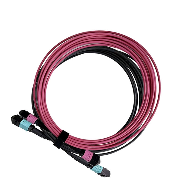
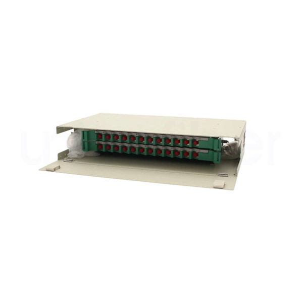
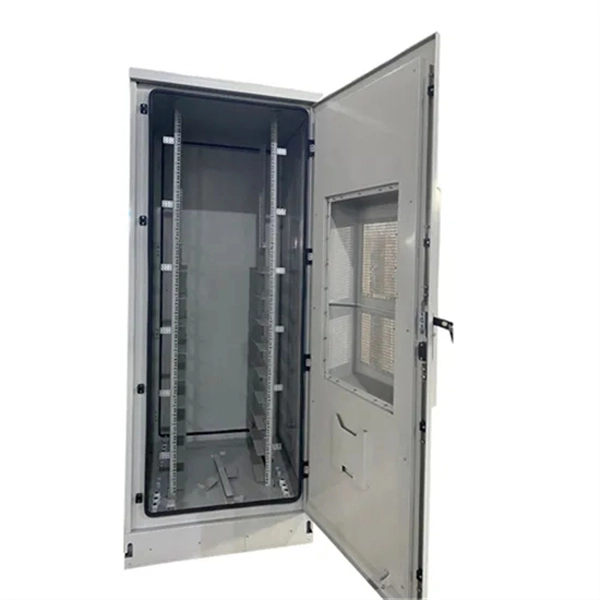
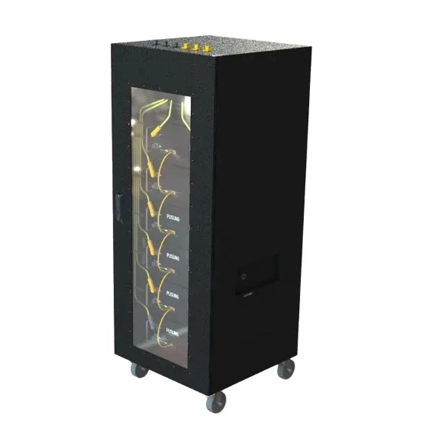
Customization Process for Low-Noise Fiber Optic Distribution Frames for Broadcast Transmission
This complete guide explores everything you need to know about ODFs — from their structure, types, and key components, to installation best practices and modern design trends. It includes first determining the type of communication system (s) which will be carried over the network, the geographic layout (premises, campus, outside. An Optical Distribution Frame (ODF) is the central hub for fiber splicing, termination, patching, and cable protection in modern optical networks. Why do operators, designers, and installers use additional fiber optic hardware racks for cable and fiber management? The active electronics are the most expensive part of the.
-
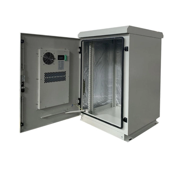
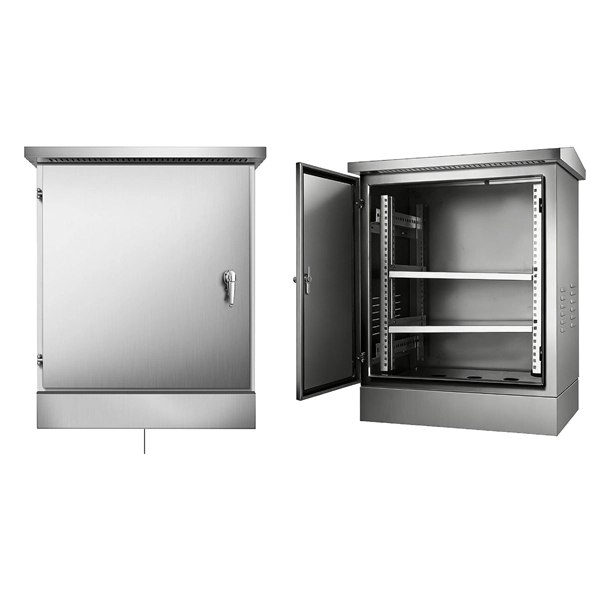
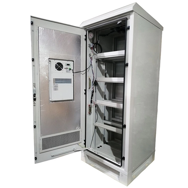
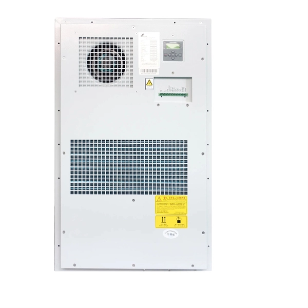
Process of making a small electrical distribution box
Construction begins by preparing the enclosure, drilling holes for the power inlet, output receptacles, and required ventilation. After smoothing the holes, mount the circuit breaker panel or rail securely inside the box, followed by the attachment of the ground and neutral bus. A distribution box is an essential component in electrical engineering, widely applied in residential, commercial, and industrial projects. It is very unique design and made by very small tools. This post is a case study of a personal project I completed based on South Korean standards (single-phase 220V / 60Hz) and is NOT a universal tutorial. Do not attempt this unless. Once I thought up the idea of the remote starter and switch stuff, i needed a way for them to not interfere with each other. Solution: diodes, the electronic one way valve.
-
The function of the light guide bar light source module
Through the light diffusion structures on the incidence surface of the light guide bar and the full-reflection action of the light inside the light guide bar, the light guide bar can provide illumination with uniform brightness; and moreover, the utilization rate of. Through the light diffusion structures on the incidence surface of the light guide bar and the full-reflection action of the light inside the light guide bar, the light guide bar can provide illumination with uniform brightness; and moreover, the utilization rate of. The invention discloses a light guide bar and a light source module adopting the same. On a cross-sectional plane of the light guiding bar, there is a first line interval on the upper surface. A second line interval, a third line interval and a. Modern light guides are used for the transportation of light signals from a circuit-board-mounted LED via a particular route to a defined light-emitting surface, with minimal loss and blurring effect. They are used to illuminate areas that are too small or too hazardous to permit the installation of a light bulb.
[PDF Version]