-
Correct Method for Testing Optical Power Meter Readings
Use an optical power meter for this task. You use it to measure the strength of light signals in fiber optic cables. The basic process is straightforward: turn the meter on, set it to the correct wavelength, clean your connectors, plug in, and read the. FOA "Quickstart Guides" are short, simple guides to basic fiber optic tests.
-
What are the testing methods for pigtail splicing
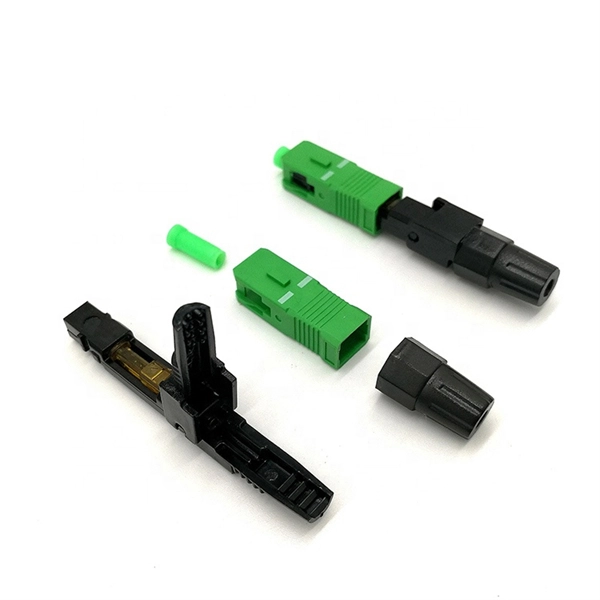
To test fibre splicer quality, begin by inspecting cleave angles and fibre cleanliness. Next, confirm arc calibration and alignment using the splicer's splice loss estimation. Follow up with OTDR or ILM testing to validate results. This guide covers everything: what fiber optic pigtails are, how they differ from patch cords, which connector and polish type to specify, how to choose between mechanical and fusion splicing, and the real-world applications where pigtails are the right call. The Contractor must utilize the correct equipment and testing techniques to gain acceptance, or the work cannot be approved. Either joining method must have three primary characteristics. The most efficient way to terminate a fiber run is by using a pigtail.
-

Indoor 4-core optical fiber cable pigtail splicing method
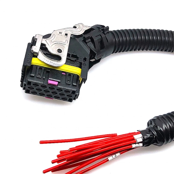
Splice pigtails onto existing fiber cables with a fusion splicer — the most time-efficient field termination method, with no polishing consumables or cure time. Field-terminating connectors is a meticulous, high-pressure process where even a tiny mistake can force you to cut the fiber and start all over again. The most efficient way to terminate a. Executive Summary: A fiber optic pigtail is one of the most commonly specified yet least understood components in structured cabling. It is typically used in cabling work area subsystems. When Do You Need to Splice Fiber Optic Cables? Fiber optic cable splicing.
-
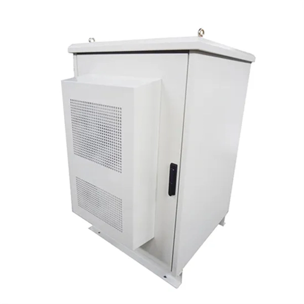
Grounding method for motor distribution box
The most common method of providing for grounding in NEMA motors is a ground lug under one of the conduit box mounting bolts. This is standard in CORRO-DUTY® motors. Each DISTRIBUTION BOX and controller must be grounded. 26 mm 2 (10 AWG) ground wire must be used, and in all other markets a 6 mm 2 must be used. Grounding of the units: Attach a ground wire from one of. Grounding is a mechanism to protect distribution equipment and people under normal operating conditions, abnormal operational (overcurrent and overvoltage) responses, and hazardous conditions such as shocks. Next, we describe directional elements suitable to provide ground fault protection in solidly- and low-impedance grounded distribution systems. The specific neutral grounding method chosen by the utility can have significant impacts on reliability of service, safety, protection coordination, power.
[PDF Version]
-
Fiber Bragg Grating Thin Film Encapsulation Method
This paper presents an effective method of encapsulation of a fiber Bragg grating (FBG) for measurements of temperature and strain. Fiber Bragg grating (FBG) sensors have emerged as advanced tools for monitoring a wide range of physical parameters in various fields, including structural health, aerospace, biochemical, and environmental applications. This review provides a comprehensive overview of FBG sensor technology. In this report, modeling and experimental results are presented for three fiber Bragg gratings that were fabricated in Newport F-SMF-28 fiber with the direct-write method. The model is based on coupled-mode theory assuming weakly guiding fibers.
-

Cost of laying optical cables using the airflow method
Prices vary based on the length of cable needed, installation method (aerial or underground), and labor rates in your area. Expect to pay $1 to $12 per linear foot, depending on project complexity and materials. By decoupling the empty microduct installation from the fiber blowing process, network operators can achieve up to 70% reduction in initial capital expenditure. Buying fiber optic installation services involves several cost components, with total price influenced by length, location, and access. Mainly manual. A fiber optic cable is made up of ultra-thin strands, each capable of carrying huge amounts of data at the speed of light. These strands are as fine as a human hair and are engineered for high-performance data transmission.
-
Switch Fiber Optic Connection Configuration Method
In this video, I'll break down 3 easy and practical ways to use fiber ports for high-speed connections: ✅ Method 1: SFP Copper Transceivers (RJ45 Media Converters) ✅ Method 2: Optical Modules + Fiber Patch Cables (LC-LC, Multimode/Singlemode) ✅ Method 3:. In this video, I'll break down 3 easy and practical ways to use fiber ports for high-speed connections: ✅ Method 1: SFP Copper Transceivers (RJ45 Media Converters) ✅ Method 2: Optical Modules + Fiber Patch Cables (LC-LC, Multimode/Singlemode) ✅ Method 3:. This tutorial will explain the steps required to configure fiber optics on a Cisco switch and ensure proper connectivity in your network. If you're looking to learn how to configure fiber optics on a Cisco switch, it's important to first configure the switch settings so it's ready for fiber optics. Fiber optic technology is widely used in networking due to its high-speed data transmission capabilities and long-distance coverage. There are no specific requirements for this document. This includes Doppler. CONFIGURING THE SWITCH IN DESIGO CC/CERBERUS DMS.
[PDF Version]
-
Installation Method of Hanging Electrical Box
In this step-by-step tutorial, we'll cover: ✅ Tools you need ✅ Safety precautions ✅ Mounting the box ✅ Wiring tips ✅ Final checks Perfect for beginners, DIYers, and electricians who want a clear installation guide. more Learn how to properly install an electrical box safely. Learn how to install a junction box safely, from choosing the right box and mounting it correctly to making secure splices and following basic code-safe practices. Installing and securing the correct box. Mounting new electrical boxes is a simple process, but the job does require careful planning. Whether you are upgrading the electrical system in an old home or planning your electrical needs for new construction, it helps to draw out your plans on paper. Here's an example: Southwire 52171-OW. They house the connections between wires, providing power to outlets, switches, and fixtures throughout your house.
[PDF Version]
-

Dual ABC method for relay protection
This paper presents an adaptive protection coordination scheme for optimal coordination of DOCRs in interconnected power networks with the impact of DG, the used coordination technique is the Artificial B.
-
Calculation method for beam splitter
A beam splitter divides incident light into reflected and transmitted beams at a specified R/T ratio. For a lossless beam splitter, R + T = 1. One of the biggest challenges for modeling such a system is that multiple ray paths cannot be simultaneously traced in Sequential Mode. Thus, multiple configurations are needed to trace rays along both the transmitted and. Three techniques to model diffractive beam splitters – two in Sequential and one in Non-Sequential modes: 2. Method A: Diffraction Grating surface and multi-configuration 2. Development steps Inserting general parameters for simulation (wavelength, aperture,. Field 1 evolves as E1 ! T E3 + RE4, where T; R are the transmission and re ection coe cients for the beam splitter. The transformation matrix is then given by. Separate (focused) beams or light points are of interest for a wide range of applications, whether for manufacturing processes, for special fiber coupling, for face recognition systems or light marker generation.
[PDF Version]
-
Microcomputer Testing of Relay Protection
For testing high-voltage microcomputer protection devices, it is recommended to use a microcomputer relay protection tester capable of simultaneously outputting three-phase voltage and three-phase current, and equipped with timing function for digital inputs. Meet all test requirements on site. It can test not only various traditional relays and protection devices, but also various modern microcomputer protections, especially for transformer differential protection and. Protective Relay Test Set, Relay Tester, Secondary Current Injection Test Kit, Microcomputer Protection Testing, 3-Phase Relay Tester Discover why selecting the right Protective Relay Test Set is critical for microcomputer protection verification. In this paper, the characteristics of the equipment itself and the external environment are comprehensively considered, and.
[PDF Version]