-
Fiber optic cable test chart to check for broken ends
Use a Fiber Inspection Microscope – 200–400× magnification reveals scratches or pits on ferrule end-face. Visual Fault Locator (VFL) – Injects a red laser (650 nm); light leakage indicates bend, crack, or break. The process of testing any fiber optic cable plant during and after installation includes all the procedures covered so far. As network speeds and bandwidth demands increase, fiber performance requirements have become more stringent. Corning recommends that all fiber optic systems be tested to a minimum set. Here are the most common fiber optic testing methods used by network professionals: Conducting a visual inspection test involves using a fiber scope or microscope to examine the endfaces of connectors for dirt, scratches, or cracks. Cable contamination can also.
-

Principle of Fiber Optic Ribbon Fusion Splicing Equipment
Fusion splice is a junction of two or more optical fibers that have been melted together. Fusion splicing is the most widely used method of splicing as it provides for the lowest loss and least reflectance, as well as providing the strongest and most reliable joint between two fibers. The goal is to fuse the two fibers together in such a way that light passing through the fibers is not scattered or reflected back by the splice, and so that the splice and the region surrounding it are almost as strong as the. Ribbon cable can be spliced more rapidly by using mass fusion splicing technique. This is. This guide reveals the secrets to fusion splicing with little fluff—just proven, straightforward techniques refined from years of work in the field. The guide provides the complete workflow, covering safety precautions, tool selection, fiber preparation, fusion operation, quality control, and. It is the process of physically welding two microscopic glass strands—each thinner than a human hair—using a 2,000°C electric arc.
[PDF Version]
-
How to connect the fiber optic test patch cord
Just use the one-jumper reference method to set the reference and an adapter to connect the jumper to the test reference cord. You can put in a fibre patch cord at home. You just need to follow easy steps and be careful. Unfortunately, equipment cords are also. Correct patch-cord installation is essential for maintaining low insertion loss, stable return loss, and long-term reliability in both indoor and outdoor fiber networks. This guide addresses expert-certified best practices applied by professionals in the telecommunications, data. Watch as we demonstrate the testing process for 12-fiber MPO patch cords using a laser source. more Watch. In today's high-performance networks, fiber optic patch cables are the lifelines that ensure smooth data flow across switches, servers, and routers. Even the most advanced optical transceivers can only perform at their peak when paired with properly installed, clean, and precisely managed fiber.
[PDF Version]
-
How to test the continuity of a multimode fiber optic cable
The three standard methods for testing fiber optic cabling are a visible light source, power meter and light source, and optical time domain reflectometer (OTDR). Fiber optic testing for continuity is crucial in ensuring that light transmits through fiber optic cables without interruptions, safeguarding seamless data transmission. As the components like fiber, connectors, splices, LED or laser sources, detectors and receivers are being developed, testing confirms their performance specifications and helps. Fiber optic testing ensures the performance and reliability of fiber optic networks. It helps minimize downtime, reduce maintenance costs, and support system upgrades or reconfigurations. If it's a long outside plant cable with intermediate splices, you will probably want to verify the individual splices with an OTDR also, since that's the only way to make.
[PDF Version]
-
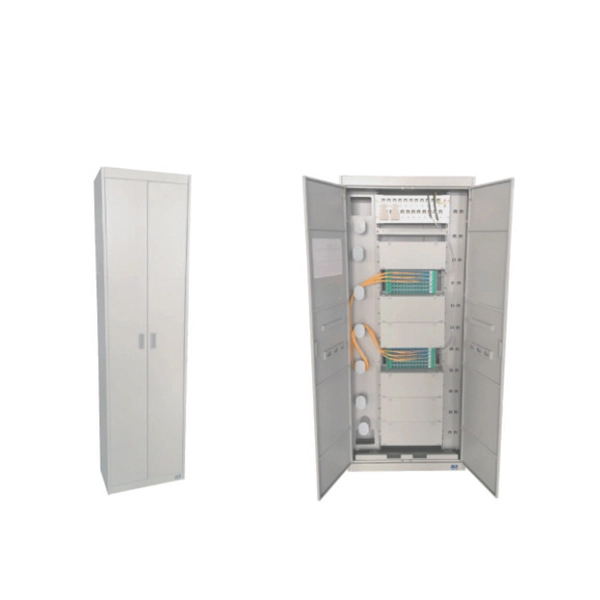
Fiber optic cable transmission between different networks
Fiber optic adapters, also known as couplers, play a crucial role in fiber optic networks by providing a connection point between two fiber optic connectors. They support high-speed, interference-resistant communication and are particularly effective in applications that require high bandwidth, low latency, and strong signal integrity. Fiber is preferred. Fiber optic cables are categorized into two primary variants: Single-Mode Fiber (SMF): With a narrow core between 8–10 microns, SMF supports long-distance transmissions by allowing only one light mode to propagate. Multi-Mode Fiber (MMF): Containing a wider core, usually 50 or 62.
-
What type of signal equipment is fiber optic cable
A fiber-optic cable, also known as an optical-fiber cable, is an assembly similar to an electrical cable but containing one or more optical fibers that are used to carry light. A TOSLINK optical fiber cable with a clear jacket. These cables are used mainly for digital audio connections between devices. Each device in the chain plays a specific role. Network designers, installers, and maintenance teams all benefit from knowing what each component. Before diving into the tools used for installation and maintenance, it's vital to understand the core components that constitute a fiber optic network. These are the physical elements that carry the light signals, enabling high-speed data transmission. In this article, we will explore the key optical equipment needed for a fiber optic network, including the Optical Network Terminal. It transmits optical signals through fiber optic cables and converts them back into electrical signals at the receiving end.
[PDF Version]