-
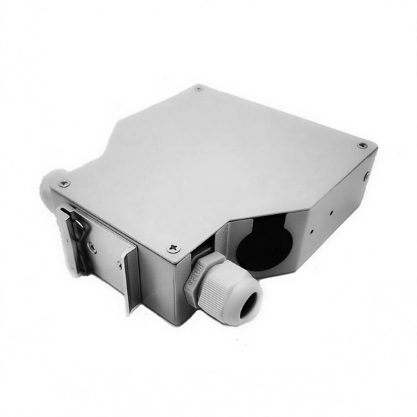
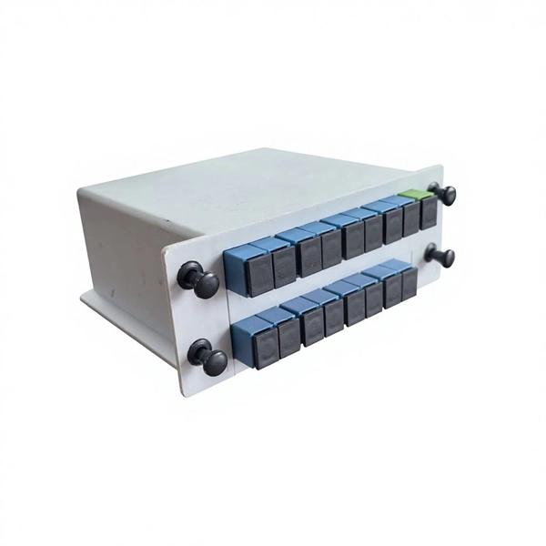
Should the cable management rack be installed in the front or the back
Leave space for cable management —especially in the back. Ensure front-to-back airflow by leaving gaps or using filler panels. This method helps maintain neatness and accessibility within the rack while ensuring efficient airflow and ease of maintenance. Both overhead and under floor pathways should be designed to support the weight of cables in the initial installation and it should also facilitate the addition of future cables. With proper design and structured tools, it helps organize cables, ensure stable signal transmission, simplify maintenance, and improve overall system. Here are some best practices for rack placement: Implementing hot and cold aisle containment is a fundamental strategy for improving airflow and cooling efficiency. The racks should be positioned in a way that optimizes.
-
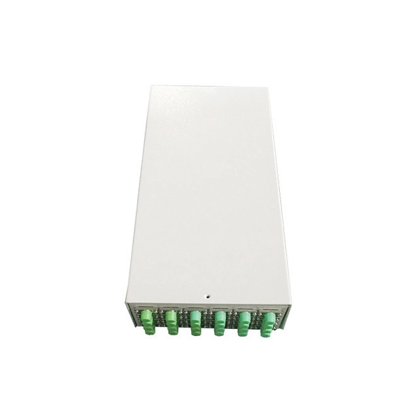
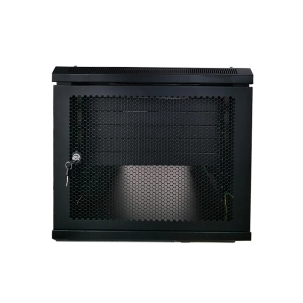
Fixing bracket on the back of the distribution box
How to install the mounting bracket? Many engineers don't know how to install this accessory. With the latest design, it can be confusing. Mounting bracket is a flexible structure, which makes it easy to adjust or replace the electrical components. All the components, wires and connections are under the protective cover due to the same height. The BBT-HF telescoping bracket, used with the BBA and BBA-4 box mounting brackets, provides an extremely flexible, fast rough-in solution. more Charlie DIYte (CharlieDIYte) tagged products below. Make sure the walls are strong enough to bear the weight of the box and electrical equipment. Ground. Electrical box screw mounts broke, can it be fixed without tearing up wall? I was unplugging an appliance in the kitchen when the whole outlet pulled out of the wall. Second photo shows my temp.
-
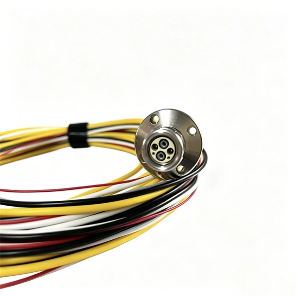
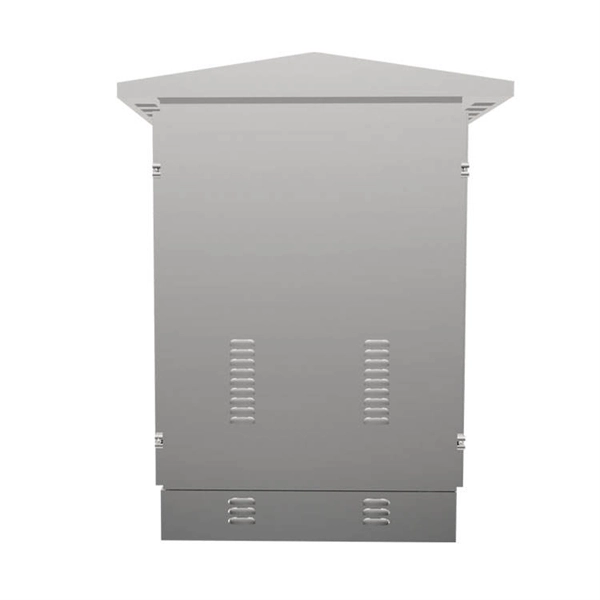
The power cable enters from the bottom of the distribution box
Cables can enter the structure from the floor (bottom entry) or from above (top entry. ) Distribution structures divide and send power to branch circuit protection devices and then to branch circuits to power downstream loads. Power. When installing a new overhead combination service for a residential service replacement we were told by the EI that we could not install our romex cables coming from under the house in a single 2" pipe approx. The scope of the article includes electrical requirements related to: Below is a complete overview. Once the box is securely in place, it's time to bring in the cables that will carry current from the main panel. Escape will cancel and close the window. Power from the utility company is typically delivered through three large conductors, which may enter the house overhead or underground. Overhead service. Fixed to a wall—This is a common approach for small electrical distribution boards. For bottom entry, the floor can incorporate a trench or false floor, which is often simpler since it provides.
[PDF Version]
-
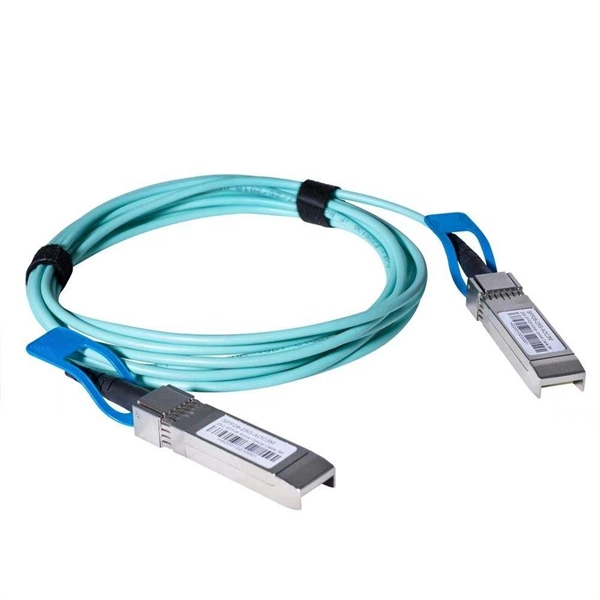
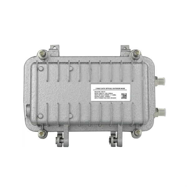
Spacing of the side of the distribution box
Side clearance: There should be a minimum of 30 inches of clearance from the sides of all electrical equipment, but in no case less than the width of the equipment itself. This is referred to as the side-to-side working space. In industrial power distribution systems, cable distribution boxes (also known as power distributor boxes, distribution electrical boxes, or electrical power distribution boxes) are the core hub of power transmission, branching, and protection. Its layout directly affects the efficiency of the. NEC Article 314 establishes requirements for the installation and use of electrical boxes, conduit bodies, fittings, and handhole enclosures. NEC Article 408. Boxes distribute low currents in an area equipped with 1 to 12 RJ 45 sockets. They centralise connections to ensure flexibility and that the installation is up to date.
[PDF Version]
-
Small busbar acceptance standards and procedures
This article details the comprehensive standards for installing and inspecting busbars, including support brackets, insulators, and bus duct systems. You'll learn essential guidelines and. For complete safety instructions and precautions, always refer to the test equipment instruction manual. This approach is applicable to all types of metal enclosed busbar. Check for physical damage/defects. Check the bus arrangement to ensure that it is consistent with the approved plans. Compliance with recognized quality standards ensures electrical safety, reliability, and regulatory acceptance, especially for telecom, data centers, and industrial electrical applications. Buyers often. IEC 61439 is a standard developed by the International Electrotechnical Commission (IEC) that covers design verification for low-voltage electrical products and assemblies. Main keywords for this article are Bus Bars and Bus Ducts Design Requirements, ANSI C37.
[PDF Version]
-
Function of the small busbar in the central power switch
The bus bar is a metal strip that distributes electrical current to the individual circuit breakers. In most assemblies you will find horizontal main bars, vertical risers, neutral and equipment-ground buses, and purpose-designed. What are Busbars, Bus Stabs, Circuit Spaces, Breaker Slots, Neutral Terminals, and Ground Terminals in an Electrical Panel or Load Center? Electric panels and load centers in residential and commercial applications have some different setting for breaker installation ad load circuit distribution. They connect directly to the main power source and are designed to handle high current loads safely. Circuit Breakers act as protective devices within the panel.
-
How to ground the busbar of the switchgear
Bus bar grounding can be achieved by one of two methods: grounding clamps applied to bus bars or a separate switchgear section with a switching mechanism dedicated to ground. In most assemblies you will find horizontal main bars, vertical risers, neutral and equipment-ground buses, and purpose-designed. The purpose of this manual is to assist the user in developing safe and eficient procedures for the installation, maintenance and operation of the equipment. For additional information, refer to NEMA Standards Publication PB2. Dive in to power up your knowledge! These guidelines govern the busbar processing and installation procedures. With the exception of SF6-to-air bushings terminals, all active portions of gas-insulated switchgear (GIS) are contained within grounded enclosures, which means that they are not susceptible to inadvertent contact. This makes gas-insulated switchgear intrinsically safe. In addition, numerous. New Approaches for Maintenance Grounding in Medium-Voltage Switchgear by Joe Richard and David Mabius Executive summary Maintenance grounding has traditionally been performed by maintenance personnel working in close proximity to open switchgear.
[PDF Version]
-
The function of the small busbar in the switch cabinet
A busbar is a metal bar, usually made of copper or aluminum, that carries electricity inside switchgear. It connects the incoming power to circuit breakers and outgoing circuits, helping power flow smoothly and evenly. Good busbar design helps prevent overheating and electrical. Busbars are the backbone of a low-voltage switchboard: rigid conductors that collect and distribute current safely between incoming devices and outgoing feeders. It connects. The use of busbar systems with their versatile rail-adaptable connection, switching and installation devices is an ideal and cost-effective electrotechnical enhancement of modern distribution boards thanks to their small footprint, modular design and quick assembly contacts. Small Busbar Room (Top of the Cabinet): Houses busbars that distribute electrical power to different sections.
[PDF Version]
-
Monaco High Voltage Busbar Processing
Our primary manufacturing processes include progressive stamping, Computer Numerical Control (CNC) bending and our RigiFlex™ technology that delivers flexible solutions. We specialize in both low- and high-volume product mix and can provide prototypes to support development. High volume busbar production: employing craft precision. Busbars are essential components in electric vehicles (EVs), which are increasingly. Intercable Automotive Solutions offers market-leading innovations for differentiated technology design and highly automated manufacturing capabilities that complement Aptiv's system-level approach to vehicle architecture design. Engineered for power distribution, they are made of copper or aluminum layers separated by insulating materials and laminated into a single structure. It is highly reliable and high-performance.