-
Cable tray horizontal tee cutting method
Completely adaptable, B-Line Flextray is designed to accommodate jobsite changes. For the best results, use a WB30BC Angular Blade Offset Bolt Cutter . to produce a clean cut. Do not use center cut style cutters, as they will leave a rough, burred cut that can damage cables and/o oximately a 45° angle. Cut the bottom wires firs in the order as shown. Flip the tray. To properly bond Hubbell ® painted cable tray, remove the plastic masking device from the trays on each end (exposing the pre-galvanized wire), and splice sections together using Hubbell ® splice kits. For cable trays that are not UL Classified as being “Suitable as an Equipment Grounding. Horizontal Tees link three 10" straight channel sections or compatible transitional fittings, enabling the creation of a sleek and efficient horizontal branch within a fiber routing system. Item code: HT Reducing Tee: W1>W2. Only two splices are required to securely connect tray widths of wire basket tray. The. Use this guide to learn the most effective installation practices when installing Cablofil tray. Engineers and contractors in North America and around the world have found.
[PDF Version]
-
Jamaican Stainless Steel Cable Tray Installation Requirements
Prepare a thorough package that includes material inspection reports, tray routing information, grounding test results, and authorized as-built drawings. Obtain permissions from the quality assurance team, EPC management, and customer representatives prior to project closure. association representing the major electrical equipment manufac-turers in the U. The Cable Tray ng standards, performance standards, test standards and application in this document have been tested extens ompetent professional en completely installed, without damage either to conductors or. Cable tray installation must comply with specific technical standards to ensure electrical safety, system reliability, and long-term maintainability. Route. The process described here takes a systematic approach to ensuring that cable tray installations meet safety, reliability, and project-specific needs while following to international standards including IEC 60364, IEEE, and IEC 60079 for hazardous locations. Ensure safe and compliant installation. QA/QC : Quality Assurance / Quality Control Engineer.
[PDF Version]
-
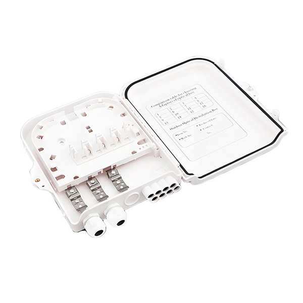
How to branch cables within a cable tray
Tees and Crosses: Create branches in the system to route cables to different areas. Reducers: Used to connect trays of different widths, often when moving from a main run (wide) to a branch run (narrow). Covers: Protect cables from falling debris, dust, moisture, and unauthorized. Let's take a closer look at the significance of managing cables in cable trays, the fundamental principles, methods, and steps required for effective implementation, as well as a case study of a successful cable management implementation. Managing cables in cable trays is not only essential for. This guide covers the critical steps, from selecting the right electrical cable tray and performing accurate cable fill calculations to managing a safe cable pull through and ensuring all bonding and grounding requirements are met. For licensed electricians, mastering these principles is essential. Installation of Cable in Cable Trays involves precise routing on support systems, NEC/IEC compliance, grounding, ampacity derating, bend radius control, segregation of services, fire safety, labeling, and reliable cable management for industrial and commercial facilities.
[PDF Version]
-
800 Cable tray fixing bracket spacing
In conclusion, the traditional guideline suggests bracket spacing of approximately every 1 to 1. 5 meters along the length of the cable tray. Weight Distribution:. The spacing between trays, whether horizontal or vertical, depends on various factors like cable type, environment, and tray material. Proper installation can significantly reduce electromagnetic interference, prevent fire hazards, and improve overall efficiency. 8 (Other Mechanical Stresses (AJ)) in that document provides requirements for cable support. Clause 522-08-04 Where conductors or cables are not supported. Cable tray (or cable ladder) systems are a popular alternative to electrical conduit systems, as they have an outstanding record for dependable service, design flexibility and cost savings in commercial and industrial applications.
-
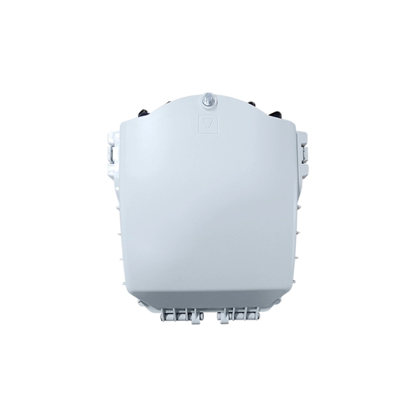
What does a fire cable tray include
Fire-resistant cable trays are engineered to withstand high temperatures, maintain mechanical integrity, and minimize fire spread. Failing to install them according to standards can lead to: Compromised fire resistance. Non-compliance with local. Cable tray systems provide a safe, organized, and flexible method for supporting insulated conductors and cables in commercial and industrial electrical installations. Understanding proper cable tray fire safety practices is essential for protecting buildings, equipment, and occupants. Commercial buildings. The resulting barrier retards the transmission of smoke, fire, and toxic gases from spreading between adjacent rooms and floors for the rated time period.
-
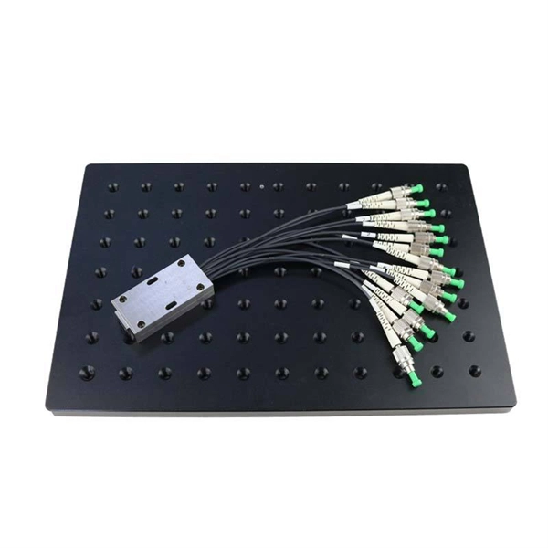
Fiber Optic Cable Tray Qualification
As outlined in the National Fire Protection Association's NFPA 70, these cables must be third-party tested and certified to ensure that they can withstand the dangers of harsh industrial environments while exposed in cable trays. The purpose of this AE Note is to outline the use of fiber optic cables in “tray rated” environments. While there are several specific types of listings for power cables, specifically for tray. d suppliers of electrical construction services. NEIS® are intended to be referenced in contrac documents for electrical construction ation or liability to users of this publication. FIBER OPTIC TRAY CABLE (FOTC) is a cable that. Ethernet cables supporting PoE lighting, IP cameras, and office network infrastructure must meet the appropriate fire and performance ratings, such as CMR (riser-rated), CMP (plenum-rated), or tray-rated, where applicable. During installation, all curvatures should be smooth.
[PDF Version]
-
How to use the cable tray accessory cable fastener
Secure Cables: Use the velcro attachments on the tray to secure power extensions, cables, and devices. Enjoy your Tidy Workspace: Revel in. Whether you're building a commercial setup or upgrading an industrial plant, proper cable tray installation ensures neat wiring, safe access, and easy maintenance. This guide breaks down the process step by step. In electrical system construction and maintenance, cable tray accessories play a critical role. These accessories serve as integral components in organizing and protecting cable lines, ensuring their efficient performance and longevity. Selecting the right cable tray accessories is crucial for the. maintain spacing or to keep cables in place when the tray is ect the minimum bend ra-dius for cables as they exit the bottom of the cable tray. In accordance with National Electrical Code (NEC) Article 392 “Cable trays” first determine the Maximum Fuse Ampere Rating or Circuit Breaker Ampere Trip Setting or Circuit Breaker Protective Relay Ampere Trip Setting for Ground-Fault Protection s the minimum.
[PDF Version]
-
Cable tray standard drawing
Download a comprehensive set of Cable Tray Installation CAD Blocks in DWG format, ideal for electrical engineers, MEP designers, and industrial layout planners. Hubbell's NEXTFRAME® Ladder Tray is the effective and widely used cable runway that supports and delivers bundles of cable between cabinets, racks, and closets, along walls, and suspended from ceilings. The Ladder Tray features light, rugged, tubular steel construction. It is designed for. us-trations without notice. All illustrations, descriptions and technical information included in this document are provided as indications and can cable trays are equivalent. The mechanical and electrical characteristics, tests, certifications, overall quality management, recommendations mentioned. Our cable tray design considerations guide details key factors to consider when designing cable tray systems for industrial and commercial applications.
[PDF Version]
-
How far is the wall support for a 200mm cable tray
The NEC requires that cable trays must be supported by members at an interval specified by the cable tray manufacturer, but not more than 5 feet for horizontal runs to support the weight of the cables and other loads. The NEC has a requirement for ladder-type cable trays. The National Electrical Code is a set of principles designed to promote public safety and welfare, as well as safeguard public health by regulating the design and operation of electrical facilities and. This is a description of how to select, install, and support these metal or plastic frames, on which electrical wires are installed. 1 Is it a. Cable Tray Support Span: The distance between supports is a critical calculation. Add Cables This calculator is provided for informational and educational purposes only. 1 Construction Manager is.
-
How to insert a pigtail from the cable tray
Strip 1/2 inch of the PVC jacket from each end. Secure the loop to the electrical unit and fasten. A switch is being used in this example. These will then be connected to the main Romex wire. Pigtailing is an essential electrical wiring technique used when adding devices or when there aren't enough spaces in a junction box. Disclaimer: Always use multiple sources and do your homework before performing any electrical work.
-
How to describe a cable tray
In the of buildings, a cable tray system is used to support insulated used for power distribution, control, and communication. Cable trays are used as an alternative to open wiring or systems, and are commonly used for cable management in commercial and industrial construction. They are especially useful in situations where changes to a wiring system are anticipated,.
-
Requirements for Cable Tray Laying Direction
Cable tray systems are recognized as a wiring method by many national and international electrical codes. Typical requirements address: Tray construction, load ratings, and materials. Support spacing, mechanical strength, and. Below is the detailed cable tray installation method statement not only for cable tray but also applicable for GI ladder and trunking for indoor and outdoor applications and in service rooms like pump rooms, electrical rooms and plant rooms etc. All materials intended for cable tray, ladder and. But before you lay the first tray or clamp down a single cable, you need a solid plan. This guide breaks down the process step by step. The National Electrical Code is a set of principles designed to promote public safety and welfare, as well as safeguard public health by regulating the design and operation of electrical facilities and.
[PDF Version]