-
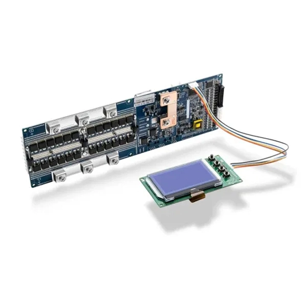
Which port on the fiber optic access switch
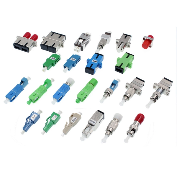
The SFP port is commonly found on Gigabit Ethernet switches and is primarily used for fiber optic device connections or for uplinking 1G switches to aggregation/core layer devices, providing higher-bandwidth links. Unlike fixed RJ45 copper ports, SFP ports support both fiber and copper modules, enabling far longer distances, greater flexibility, and improved scalability in enterprise. It introduces common Ethernet switch port types. We will look at data rates, functions, and network architecture. This guide is especially useful when selecting a 1G campus switch or upgrading to higher-performance Ethernet solutions. They come in various form factors such as SFP, SFP+, QSFP+, and XFP. Switches with SFP ports can. The Gigabit Interface Converter (GBIC) or Small Form-factor Pluggable (SFP) port is a modular interface that offers flexibility to network administrators in terms of their networking hardware. These ports use twisted-pair copper cables (Cat5e, Cat6, Cat6a, etc.
[PDF Version]
-
Plug an optical module into both ends of the optical fiber
Do not insert the optical module with optical fibers directly into an optical interface. From enterprise access networks to large-scale data centers, SFP modules allow network. In high-speed data networks, the seamless integration of fiber optic cables with SFP (Small Form-Factor Pluggable) modules is critical for reliable signal transmission. However, with a bit of guidance, the process is straightforward. This article will walk you through the necessary steps to ensure a successful connection. This optical transceiver tutorial will introduce how to install SFP module, how to remove SFP module, and give some insights on the operation precautions.
-
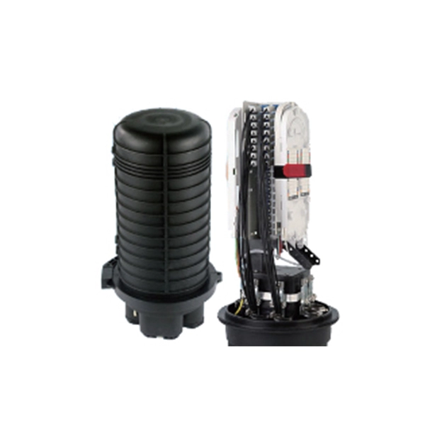
Why is optical fiber splicing divided into directions
Two sources of loss caused by mismatched fibers are directional; numerical aperture (NA) and core diameter differences inherent in the fibers being joined. Differences in these two will create connections that have different losses depending on the direction of light propagation. This is essential for extending network reach, repairing breaks, or connecting cables in data centers and telecom infrastructure. The goal is to align the microscopic glass cores (typically. This is where fiber optic cable splicing—the process of creating a permanent, high-performance join between two fiber ends—becomes critical. For network managers and technicians, a poor splice can lead to significant signal degradation, network downtime, and costly troubleshooting. The fiber optic cables of various lengths like more than 5kms, 10kms, etc.
-
What are the specifications and parameters of multimode optical fiber
Multimode Fiber (MMF) has a core diameter, typically 50–100 micrometers, has ability to transfer multiple modes of light through the fiber core, uses lower-cost electronics (LED, VCSEL) operates at the 850 nm and 1300 nm wavelength and is used for short distance interconnections. Multimode Fiber (MMF) has a core diameter, typically 50–100 micrometers, has ability to transfer multiple modes of light through the fiber core, uses lower-cost electronics (LED, VCSEL) operates at the 850 nm and 1300 nm wavelength and is used for short distance interconnections. Multi-mode optical fiber is a type of optical fiber mostly used for communication over short distances, such as within a building or on a campus. Multi-mode links can be used for data rates up to 800 Gbit/s. In most cases, that number of guided modes is large, e. Figure 1: A single-mode fiber (left) has a core which is very small compared. Multimode fiber works well for short to medium distances, providing scalable capacity and cost-effective deployment for data centers, office buildings, and campuses. Designs under development are listed below.
[PDF Version]
-
Optical Cable Positioning and Injection Method Operation
In fiber optic cable blowing, high-speed airflow is combined with a mechanical pushing force to produce the installation, known as blowing or jetting. This is the preferred method for pushing fiber optic cable thr.
-
Cable and Optical Fiber Laying Methods
This comprehensive guide examines all major fiber installation methods, from underground trenching to submarine cable laying, providing technical insights drawn from industry best practices and real-world deployment experiences. We should always consider the restrictions established by different administrations related to this matter. Starting with site surveys and permissions, to installing fiber optic cable and emphasizing the process as a key stage in mastering fiber optic installation, to the careful handling of cables and high-stakes splicing, each stage is critical. Whether you're a technician, a network planner, or simply curious about fiber optic technology, this article will. This comprehensive guide explores the essential processes and best practices for underground fiber optic cable installation, helping business decision-makers understand the investment required to upgrade their telecommunications infrastructure.
[PDF Version]
-
How to coil the fiber optic cable at the end of the optical fiber
For overly long or short fibers, coil them separately at the end. Before fiber coiling, the optical cable and pigtail should be pre-processed, and the optical cable and pigtail should be opened first. The key step is to calculate the reserved length and then splice the optical fiber. The success rate of optical fiber splicing is very important, because once the. Splice fiber optic cables follows these steps: stripping, cleaving, splicing, and coiling. When done right, splicing ensures minimal loss and long-lasting performance. This guide will walk you.
-

How to connect a switch to a fiber optic cable box
Connect the fiber optic cable: Attach the fiber optic cable's connector to the transceiver module on the switch. Make sure the connector type (e. Network topology refers to the way in which the links and nodes of a network are arranged in relation to each other. SFP transceiver modules are specific to the type of fiber being connected. Fiber optic cabling is increasingly used to connect network switches and other datacom equipment, especially in long-distance and mission-critical applications. Most modern fiber-enabled network switches require an SFP transceiver module. Connecting a fiber optic switch involves several steps, ensuring compatibility between the switch's ports and the fiber optic cable.