-
Fabrication of Fiber Optic Pigtails
This guide covers everything: what fiber optic pigtails are, how they differ from patch cords, which connector and polish type to specify, how to choose between mechanical and fusion splicing, and the real-world applications where pigtails are the right call. Get the wrong connector type, the wrong polish, or skip proper fusion splicing technique—and you're looking at elevated signal loss, increased back reflection, and a. This technology aligns fiber pigtail arrays for coherently combining different optical beams, reducing deviation in virtual beam waist position among endcapped fibers. Pigtails are fiber optic cables which are only terminated on one end. The success of a network in fiber optic cable installation heavily. Our Fiber Optic Patch Cord Production Line equipment includes everything needed to manufacture high-quality patch cables and pigtails: from cable making machines and pneumatic crimpers to precision polishing fixtures and IL/RL test stations. The connector end can be linked directly to network equipment, while the exposed end can be spliced to another fiber optic cable.
[PDF Version]
-
Fiber optic pigtails Network and carrier grade
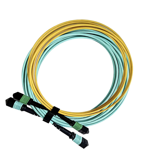
In this comprehensive guide, we will explore the different types of fiber optic pigtails, including LC, ST, and SC pigtails. Each type has its own unique design, size, and compatibility features. 5m to 2m—that has a factory-terminated connector on one end and bare fiber on the other end. The bare fiber end. A pigtail fiber indicates a short length of optical fiber cable that has a pigtail connector (for example, SC, FC, ST, LC, etc. Get the wrong connector type, the wrong polish, or skip proper fusion splicing technique—and you're looking at elevated signal loss, increased back reflection, and a. IDEAL FOR CATV, FTTH/FTTX, TELECOMMUNICATION NETWORKS, DATA PROCESSING NETWORKS, LAN/WAN NETWORKS.
-
What are the splicing methods for fiber optic pigtails
You have two methods: fusion splicing and mechanical splicing. The right choice depends on your performance requirements, budget, and the volume of splices you're performing. Fusion splicing uses a precision arc discharge between two electrode rods to heat and fuse the cleaved fiber. Get the wrong connector type, the wrong polish, or skip proper fusion splicing technique—and you're looking at elevated signal loss, increased back reflection, and a field termination that fails certification. This guide covers everything: what fiber optic pigtails are, how they differ from patch. The most efficient way to terminate a fiber run is by using a pigtail. Each fiber is marked “A” or “B”, or different colored connector boots are used to mark polarity. Similarly, 4, 6, 8, 12, 24, and 48 fiber. In this guide, we cover the basics of fiber optic splicing, how to perform splicing using two different methods, and finally some best practices to perform good fiber splicing. Either joining method must have three primary characteristics.
[PDF Version]
-
Laying pigtails and installing fiber optic patch cords
This guide covers everything: what fiber optic pigtails are, how they differ from patch cords, which connector and polish type to specify, how to choose between mechanical and fusion splicing, and the real-world applications where pigtails are the right call. Today, I'll show you how to pick the right patch cord or pigtail — step by step. A Fiber Patch cord connects two devices. It's ready to use out of the box. Mixing them up drives costs higher, increases loss, and slows your rollout. Remove the outer coating carefully to expose the fiber. Align and fuse the pigtail fiber with the main. In this detailed video, we'll walk you through the fiber optic pigtail splicing process — from preparation to final testing. If you're new to fiber optics or want to enhance your technical skills, this guide will help you understand how to splice fiber pigtails safely and efficiently.
[PDF Version]
-
What are the methods for splicing fiber optic pigtails during fiber optic cable installation
The two primary industry-accepted methods for fiber optic cable splicing are fusion splicing and mechanical splicing. The choice between them depends on performance requirements, budget constraints, and the specific application environment. A fiber optic pigtail is a short length of optical fiber cable with a factory-terminated connector on one end and a bare, exposed fiber on the other. Instead of building a connector from. Fiber optic splicing plays a vital role in modern communication networks by enabling seamless connections between fiber optic cables.
-
Fiber Optic Cable Signal Tester
Fluke Networks is a market leader in enterprise fiber testing equipment, with a wide range of field-tough fiber testers to help you inspect, clean, verify, certify, and troubleshoot your fiber optic cable networks.
-

Fiber optic cable does not support 1550
Multimode fiber is designed to operate at 850 and 1300 nm, while singlemode fiber is optimized for 1310 and 1550 nm. One of the major advantages of 1550 nm transmission is compatibility with Erbium-Doped Fiber Amplifiers (EDFA). All Singlemode fibers work very similarly in either wavelength—that is, you don't need to buy fiber based on wavelength, one fiber fits all. So, IF your cable assembly is built. This article delves into why 850, 1310, and 1550 nm are standard, what less-known regimes and tradeoffs exist, and how an OEM fiber-cable manufacturer can design and test with wavelength considerations built in. Consider the balance between attenuation and dispersion when designing your network for optimal performance.
-
Single-mode port connected to multimode fiber optic cable
Single mode and multimode fiber cables are quite different when it comes to size, light source, signal, and so on. So, they definitely are not interchangeable, and compatibility issues can occur when you try to connect a single mode fiber optic connector to a multimode network. This is where fiber conversion comes in. Single-mode. To realize the short-range direct connection to the end B switch with the same port, the same 10GBASE-SR SFP+ module should be plugged into the end B switch port. What if end B is located in. It's possible because Multi-mode optical cables have a very wide fiber core – 62. Understanding the key differences between these two technologies is essential for IT professionals, business owners, and even homeowners looking to future-proof their network.
-
Requirements for installing fiber optic cable poles
Comply with National Electrical Code requirements for cable ratings and fire safety. Prepare cable ends by sealing gel-filled cables and protecting buffer tubes to prevent water ingress and physical damage. You must follow strict installation guidelines for outdoor fiber optic. The Fiber Optic Association, Inc. (FOA) was founded in 1995 to help develop the workforce to build the fiber optic networks to support a rapid expansion in communications and the Internet. FO-VC2 JOINT USE - VERICAL MIDSPAN CLEARANCES 48. Since outside plant fiber optic networks can cover a broad range of installation types using varied components over different types of geography, it is impossible to. Let's discuss fiber optic installation requirements and best practices for a seamless installation. Engineers and. Some of the common tools include aerial storage for cables; telescoping poles; fiber heat shrink tube; brackets; blocks; cable saddles; fiber suspension clamp; cable rings, horizontal fiber splice closure, dome fiber splice closure, fusion splicers, etc.
[PDF Version]
-

Fiber Optic Channel Sharing
The goal of Fibre Channel is to create a storage area network (SAN) to connect servers to storage. The SAN is a dedicated network that enables multiple servers to access data from one or more storage devices. Enterprise storage uses the SAN to backup to secondary storage devices including disk arrays, tape libraries, and other backup while the storage is still accessible to the server. Servers ma. OverviewFibre Channel (FC) is a high-speed data transfer protocol providing in-order, lossless delivery of raw block data. Fibre Channel is primarily used to connect to in (SAN) in co. When the technology was originally devised, it ran over optical fiber cables only and, as such, was called "Fiber Channel". Later, the ability to run over copper cabling was added to the specification. In order to avoid confu.
-
Are fiber optic cables beneficial for routers
Fiber routers are known for their reliability, as fiber optic cables are less prone to interference and signal degradation compared to traditional copper cables used in normal routers. It's not just an incremental upgrade; it's a fundamental shift in how we access the digital world. By 2025-26, fiber deployment continues to accelerate, with projections. Fiber optic internet delivers blazing-fast speeds and reliable connectivity, making it a top choice for modern homes and businesses. However, setting up a fiber optic connection to your router can seem daunting if you're unfamiliar with the process.