-
Is fiber optic temperature measurement single-mode
Distributed fiber-optic temperature sensors can be realized with ordinary single-mode fibers, not containing any special structures such as fiber Bragg gratings. In many cases, one uses telecom fibers, operated in the 1. Our company has independently developed the DTS-BLY-5S (SMV), which features low power consumption of as low as 6W, a three-proof motherboard (anti-fungus, moisture-proof, and salt spray-proof), a temperature sensing distance of over 24 km, a maximum of 16 channels, compatibility with fiber cables. Optical temperature sensors are temperature sensors which are based on optical technology — in most cases, on fiber optics. Learn more about the ODISI for high-definition temperature measurement Strain sensors based on. In this paper, the self-phase modulation (SPM) effect in a double-cladding single-mode tellurite optical fiber (DC-SMTOF) was exploited for temperature sensing. Modes are the possible solutions of the Helmholtz equation for waves, which is obtained by combining. It is a single point contact temperature measurement system. The light source is used to excite the Fluorescent material.
[PDF Version]
-
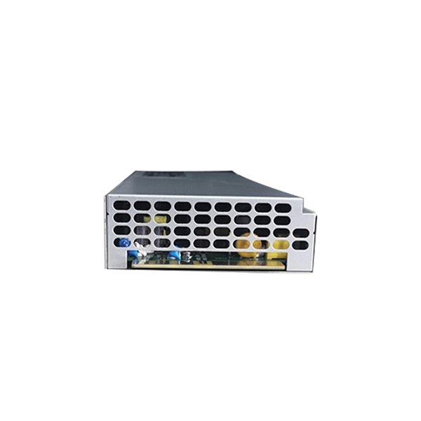
How to connect the power supply to a fiber optic switch
We'll show you how to connect power and network using a fiber optic cable linked to the core switch in the control room. No extra adapters needed—just plug directly into an AC outlet. This setup is perfect for extending your network to outdoor IP cameras or remote locations. more Learn. Fiber connectivity to the power supply will pass through a standards-based SFP (small form-factor pluggable) interface which allows operators to communicate with the power supply using their chosen vendor solution. The opportunities and efficiencies they offer speak for themselves—but, as they spread to locations both indoors and out, you're probably feeling the crunch caused by not having enough. While in this post, we mainly focus on the PoE system that using fiber optic with power to solve unusual applications specifically in real life, which may need to achieve greater distance, higher bandwidth, or better reliability. Concerns go from laying. CONFIGURING THE SWITCH IN DESIGO CC/CERBERUS DMS.
[PDF Version]
-
Can a static fiber optic cable be connected to a router
You can't directly connect a fiber optic cable to your router. You need an intermediary device. This comprehensive guide combines industry standards with field-tested practices to ensure you achieve a rock-solid. To connect your fiber optic cable to a router, ensure you have the following: Fiber optic modem (ONT): Most fiber connections require an Optical Network Terminal (ONT), provided by your ISP. The fiber line terminates at the Optical Network Terminal (ONT), which is typically supplied and installed by the internet service provider.
-
Where should a gigabit router be plugged into a 500m fiber optic connection
Fiber optic modem (ONT): Most fiber connections require an Optical Network Terminal (ONT), provided by your ISP. Compatible router: Verify that your router supports fiber optic input (look for an SFP or WAN port labeled "ONT" or "Fiber"). This. The two most common types of Ethernet speeds are Fast Ethernet (10/100Mbps) and Gigabit Ethernet (10/100/1000Mbps), which are more than enough for most people's local network uses. But as the internet access increases, the network speed decreases gradually since Ethernet cannot handle such heavy. An experienced installer knows to use Ethernet switches to extend connections and with the advent of PoE powered switches this even negates the need for an AC electrical outlet to power up the remote switch. Else any of. This article breaks down scientifically validated rules for optimal router positioning, supported by engineering data, peer-reviewed studies, and practical deployment experience. A modern Wi-Fi router is capable of far greater performance than most households ever experience.
[PDF Version]
-
AI-powered Fiber Optic Cable Maintenance
By integrating Fiber Optic Internet with AI-powered predictive maintenance tools, organizations can monitor their equipment in real-time and anticipate potential failures before they occur. To keep up with this rapid growth, the integration of cutting-edge technologies like Artificial Intelligence (AI) and Machine Learning (ML) is essential for optimizing. This article explores how AI's exponential growth is creating transformative demands on fiber optic cables, connectivity solutions, and the broader communications industry, and what innovative approaches manufacturers must adopt to meet these challenges. Machine learning models can adapt their behavior to changing network conditions, traffic patterns.
-
How to connect fiber optic cable to switch 6
Connect the fiber optic cable: Attach the fiber optic cable's connector to the transceiver module on the switch. Make sure the connector type (e. Network topology refers to the way in which the links and nodes of a network are arranged in relation to each other. Simply put, it defines how network. In this guide, we'll walk you through how to connect a fiber optic cable to a router safely and efficiently. Advantages Determine the length of the fiber run and choose either multi mode for runs under 1000 feet or single mode for runs over 1000 feet.
-
The function of fiber optic laser diodes
Laser diodes are the enabling technology that makes fiber networks scalable: they efficiently generate the precise wavelengths needed for modern transceivers, support high data rates, and allow multiple channels to coexist on the same fiber. Fiber-coupled laser diodes are gaining popularity due to their versatility across industries. With this article, we will explore the principle types, applications, and the reasons that make them supremely useful. The knowledge will guide businesses to harness the power of laser diodes along with. The laser output is then modulated so “1s and 0s” ride on light, travel through the fiber, and are converted back to electrical form at the receiver. They contain a spool of fiber optic cable which has a core that has been doped with a variety of rare earth elements from the lanthanide family of the periodic. Definition: diode laser devices where the generated light is coupled into an optical fiber Alternative term: pigtailed diode lasers Concept tree: Related: laser diodes fibers beam quality brightness polarization of light Page views in 12 months: 2585 DOI: 10.
[PDF Version]
-
How to route fiber optic cables for high-voltage power lines
This technique takes a small, lightweight fiber optic cable and wraps it around or lashes it to the power line. The cable is called optical power attached cable (OPAC), and it is lashed to the power cable with a specialized tool that is pulled from the ground, such as a. Installing ADSS (All-Dielectric Self-Supporting) cables near live power lines demands precision, compliance with safety standards, and an understanding of high-voltage risks. This guide from GL FIBER breaks down the process into actionable steps, aligned with IEEE 524 and IEC 61935-1 protocols, to. Most aerial fiber optic cables are installed by lashing to a steel messenger wire strung between poles, but there is a category of cables with special high-strength jacket designs called all-dielectric self-supporting (ADSS) cables. ADSS cables are designed to withstand very high-tension loads. bles in a high voltage environment, with typical line voltages of 115 kV or more, requires the evaluation of certain critical parameters. Curr ntly, there are a limited number of industry documents that address the requirements for optical fiber cables near high voltage circuits.
[PDF Version]
-

Fiber optic cable does not support 1550
Multimode fiber is designed to operate at 850 and 1300 nm, while singlemode fiber is optimized for 1310 and 1550 nm. One of the major advantages of 1550 nm transmission is compatibility with Erbium-Doped Fiber Amplifiers (EDFA). All Singlemode fibers work very similarly in either wavelength—that is, you don't need to buy fiber based on wavelength, one fiber fits all. So, IF your cable assembly is built. This article delves into why 850, 1310, and 1550 nm are standard, what less-known regimes and tradeoffs exist, and how an OEM fiber-cable manufacturer can design and test with wavelength considerations built in. Consider the balance between attenuation and dispersion when designing your network for optimal performance.
-
Extinction Ratio of Fiber Optic Sensors
In the world of fiber optics, the extinction ratio is a critical yet often overlooked parameter that can make or break signal integrity. This article explains what extinction ratio is, why it matters for reducing bit error rates in optical communication, and how it impacts optical module. Comprehensive Guide to Polarization Extinction Ratio in Fiber Optic Sensor s Introduction to Polarization Extinction Ratio The polarization extinction ratio (PER) is a critical parameter in fiber optic sensors that measures the degree of polarization extinction between two orthogonal polarization. Extinction ratio measurement at the connector level can quickly reveal alignment issues. The polarization axes of both fibers must be aligned before fusion. A poorly aligned splice is one of the most common sources of PER loss in. Cross coupling in regards to a birefringent fiber, quantified by extinction ratio, indicates the amount of light which is able to mix between the two polarization axes. To overcome this limitation, we propose and demonstrate a novel resonator design with an intrinsically high polarization.
[PDF Version]
-
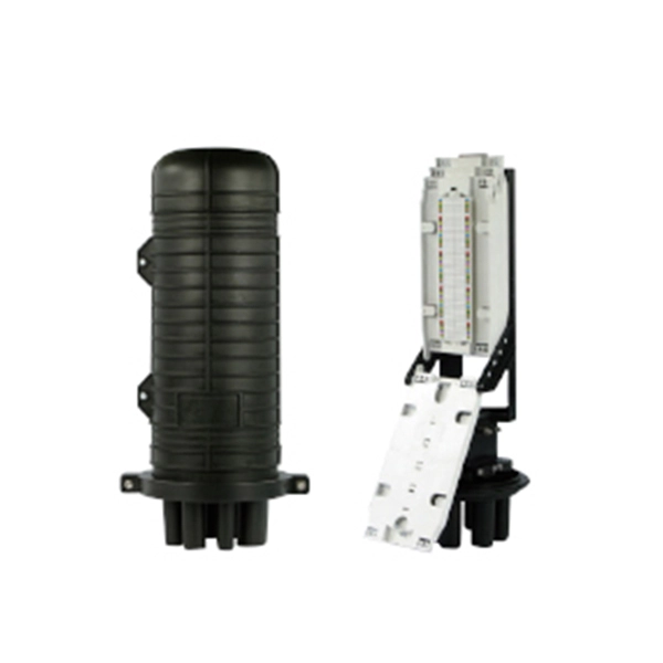
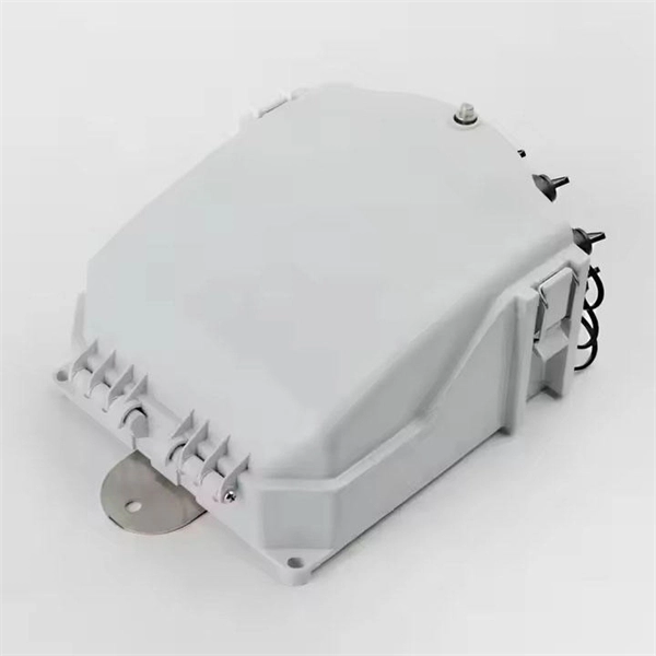
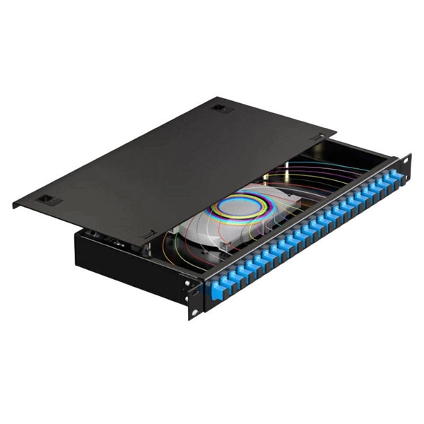
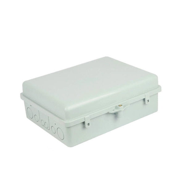
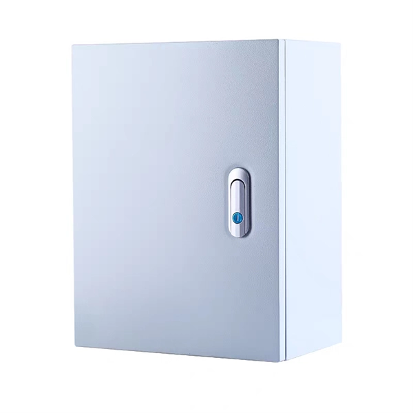
The function of the fiber optic cable protection box
They provide a secure, organized, and stable environment for the sensitive points within a fiber network—splices, connectors, and distribution points—safeguarding them from a multitude of external threats. For any organization deploying or maintaining a fiber network, understanding the role and. Fiber Connection Protection Box is a device designed for fiber optic line terminal connection and protection and is widely used in fiber optic communication systems such as fiber to the home (FTTH), local area network (LAN), and metropolitan area network (MAN). Its main functions can be summarized as follows: 1. Fiber closure protects spliced fibers in backbone and feeder lines, fiber box (or fiber distribution box) organizes and splits fibers in.