-

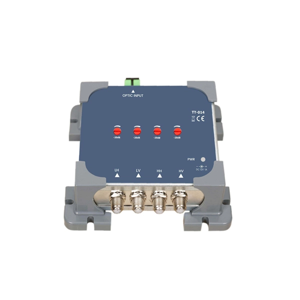
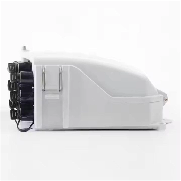
What is a fiber optic coupler alignment tool
Fiber alignment stages are multi-axis positioning stages featuring smooth, continuous motion with micron or sub-micron resolution and long-term stability, which are the mechanical properties required to couple light from optical fibers to waveguides or other fiber optic components. Thorlabs offers. OZ Optics' alignment kits simplify the task of coupling lasers or laser diodes to either singlemode or polarization maintaining (PM) fibers. With a V-Groove design, these tools ensure stable alignment, reducing signal loss and enhancing coupling efficiency. Fast, low loss temporary splices with.
-
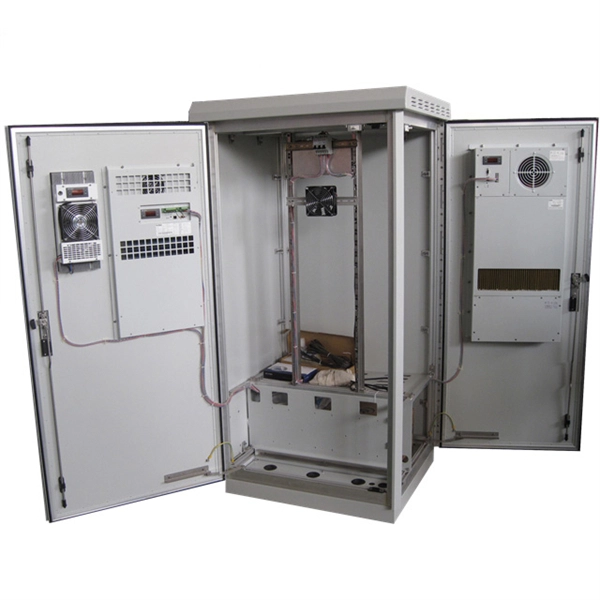
Fiber Optic Sensing Smart Pipeline Network
How can operators detect pipeline threats before they become costly failures? This article explores how distributed fiber-optic sensing redefines pipeline safety and reliability by enabling real-time monitoring, early leak detection, and proactive maintenance. Pipeline operators and LNG terminal operators face unique and demanding challenges. Based on our various distributed fiber optic sensing patented technologies, it relies on the use of our interrogators: The. range, and typically measure only a single parameter at a time.
-
Single-mode port connected to multimode fiber optic cable
Single mode and multimode fiber cables are quite different when it comes to size, light source, signal, and so on. So, they definitely are not interchangeable, and compatibility issues can occur when you try to connect a single mode fiber optic connector to a multimode network. This is where fiber conversion comes in. Single-mode. To realize the short-range direct connection to the end B switch with the same port, the same 10GBASE-SR SFP+ module should be plugged into the end B switch port. What if end B is located in. It's possible because Multi-mode optical cables have a very wide fiber core – 62. Understanding the key differences between these two technologies is essential for IT professionals, business owners, and even homeowners looking to future-proof their network.
-
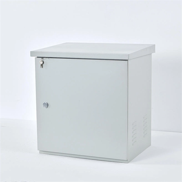
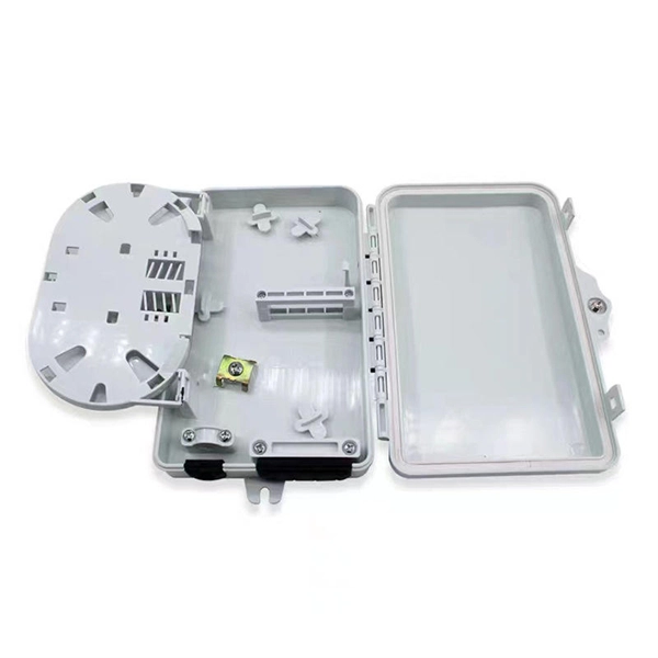
How to deal with abnormal noises from fiber optic terminal boxes
From SPL meters to spectrum analyzers, technology provides the means to uncover these invisible nuisances. Once identified, simple yet effective measures like relocation, soundproofing, and firmware updates can mitigate their impact. A fiber termination box is the standard instrument used in fiber optic networks to connect, secure, and protect optical fibers at the terminating point. When issues like signal loss, slow speeds, or intermittent connectivity arise, systematic troubleshooting is key. Before. Proper troubleshooting can help quickly identify and resolve issues to minimize downtime.
-
Fiber optic cable connected to router then connected to switch
If using a network switch with SFP ports, insert the fiber optic transceiver into the SFP port and connect the fiber optic cable to the transceiver. Connect the other end of the Ethernet cable to your network device, such as a computer, router, or. Fiber Optic Transceiver: Often used with media converters or network switches, these devices convert electrical signals to optical signals and vice versa. Patch Panel. As we speak I just have optic fibre (Community Fibre) connected to my Huawei modem / Linksys Velop which will be connected to a new POE switch (need to identify the best model to be compatible with my optic fibre extension project). Network topology refers to the way in which the links and nodes of a network are arranged in relation to each other. Use a standard Ethernet cable (Cat5e/Cat6) to.
[PDF Version]
-
Invisible fiber optic cable can be connected to a network port panel
The short answer is no - RJ45 connectors are designed for electrical Ethernet signals, while fiber optics transmit light pulses through glass or plastic. However, modern networks often combine both technologies. In this article, we'll explore the ins and outs of FTTR Invisible. There are endless ways to configure a fiber-optic network, but here are a few simple ways to add fiber to your existing network., Cat 6a) to fiber and back again. If category cable is used, doesn't that negate the benefits of the fiber? Fiber provides a much cleaner installation due to its size and is 'future proof'.
-
What is the appropriate height for optical fiber cables
Based on my first-hand, environmental testing of the declination of the ceramics under pressure and under temperature, I recommend targeting a fiber height of +/-20 nanometers. The Fiber Optic Association, Inc. (FOA) was founded in 1995 to help develop the workforce to build the fiber optic networks to support a rapid expansion in communications and the Internet. The charter of the FOA was to promote professionalism in fiber optics through education, certification, and. Fiber height is a critical geometry parameter (along with Radius, Angle/Apex, and Key Error), which directly impacts the optical performance of the connector in the fiber optic network. Failure to follow these guidelines may result in damage or attenuation increases of the optical fiber or cable. Proper industry. cations, security, control and similar purposes. FO-VC2 JOINT USE - VERICAL MIDSPAN CLEARANCES 48.
[PDF Version]
-
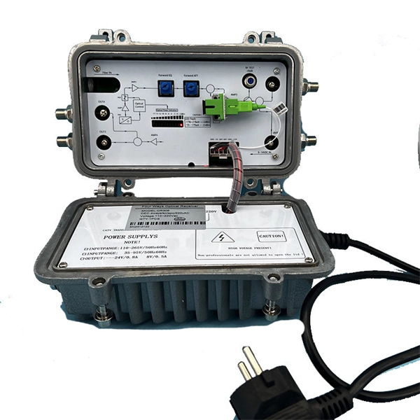
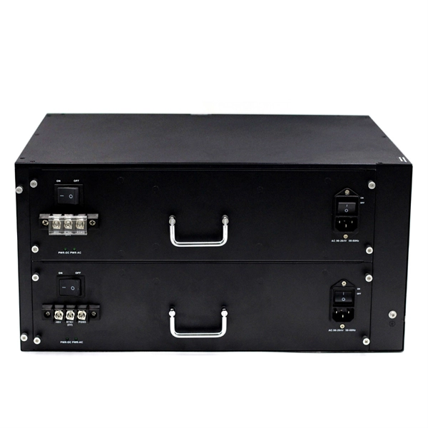
Requirements for Light Sources in Fiber Optic Sensors
The source used for a fiber optic transmitter needs to meet several criteria: it has to be at the correct wavelength, be able to be modulated fast enough to transmit data and be efficiently coupled into fiber. Jose Miguel Lopez-Higuera: Handbook of Optical Fiber Sensing Technology, John Wiley & Sons, 2002. P 603 Radiation absorption excites an orbital electron to a higher energy level. Radiation absorption creates electronic excited states that are trapped by localized defects for extended periods of. Although the IEEE-SA Industry Connections activity members who have created this Work believe that the information and guidance given in this Work serve as an enhancement to users, all persons must rely upon their own skill and judgment when making use of it. IN NO EVENT SHALL IEEE OR IEEE-SA. A Fiber Sensor is a type of Photoelectric Sensor that enables detection of objects in narrow locations by transmitting light from a Fiber Amplifier Unit with a Fiber Unit.
[PDF Version]
-

Is fiber optic cable installation a good or bad thing
Instead of sending electrical signals over metal cables, fiber transmits data as rapid pulses of light through flexible, microscopic glass strands. The result is unparalleled speed and reliability. However, jumping to this technology is not a flawless solution for every home. These tiny fibers can transmit signals of light across vast distances, capably functioning as the superior data transmission standard. There are many advantages but there are some disadvantages also, so we are going to look at the fiber optic cable advantages and disadvantages. 1) Connection Quality: Fiber optics are resistant to electromagnetic interference and have a low rate of bit error. A fiber optic cable is formed by drawing glass or a special sort of plastic, which can transmit light from one end of the fiber to a special end.
-
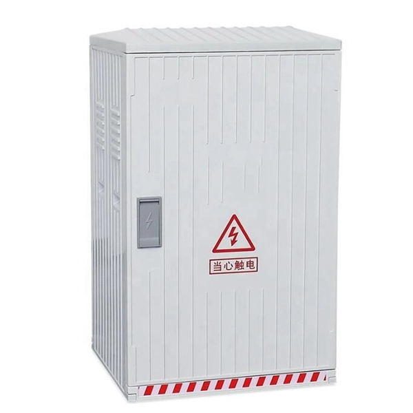
Can fiber optic cables be run alongside 35kV power cables
General Consideration: It is generally not recommended to run fiber optic cables in the same conduit as electrical power cables. This is due to several potential risks and complications that can arise from such an arrangement. When a communications cable runs parallel and in close proximity to a power cable, these magnetic fields induce unwanted currents—a phenomenon known as inductive coupling—into the sensitive data conductors. This induced noise can. TECHNICAL GUIDELINE July 30, 2020 TG030 Rev. Electrical Interference: Electrical cables can produce electromagnetic. Maintaining proper separation between power, data, and limited energy cabling is foundational to system performance, safety, and code compliance. Other than that you haven't provided much information, given. Laying network cables parallel to electrical cables is often necessary due to space constraints but comes with its own set of challenges, primarily due to electromagnetic interference (EMI).
[PDF Version]