-

What are the methods for fiber optic cable core splicing
The two primary industry-accepted methods for fiber optic cable splicing are fusion splicing and mechanical splicing. The choice between them depends on performance requirements, budget constraints, and the specific application environment. For network managers and technicians, a poor splice can lead to significant signal degradation, network downtime, and costly troubleshooting. Ensure Your Splicing Tools are Clean – #2. Use and Maintain Your. Fiber optic splicing plays a vital role in modern communication networks by enabling seamless connections between fiber optic cables.
-
One fiber optic cable core is broken
This guide provides a detailed roadmap for locating and fixing fiber optic cable breaks, covering detection techniques, repair methods, and best practices. Accidental cuts, breaks, or other damage can disrupt your network and cause costly downtime. With the right tools and techniques, you can efficiently repair damaged fiber cables and restore. In today's hyper-connected world, fiber optic cables serve as the lifelines of high-speed data transmission, powering everything from global telecom networks to local FTTH (Fiber to the Home) systems. However, a break in these delicate glass strands—whether from construction mishaps, environmental. Fiber optic cables are typically damaged in one of two ways: A premade fiber optic cable suffers connector damage when too much pull-force is applied during installation. This can occur on long cable runs through tight conduit or duct, and also if the cable becomes caught or snagged. A fiber optic. These cables consist of a core (glass or plastic) that carries light signals, surrounded by cladding to reflect light inward, a buffer for protection, and an outer jacket for durability.
[PDF Version]
-
Optical fiber cable silicon core tube communication line
HDPE Silicon Core Pipe is a high-performance conduit specially designed for optical cable protection. Size: 32/26, 34/28, 40/33,46/38, 50/41, 63/54 3. CO (Certificate of Origin): China, CO could be provided by free. ISO9001, OHSAS 18001, ISO14001, ISO45001, CE. Fiber Optic telecom, Communication, Cable. HFCL is recognized as one of the largest manufacturers and suppliers of fiber optic cable across the globe, providing high-quality products and reliable services. Adhering to stringent quality standards, our cables are Telcordia GR-20-CORE and ICEA S-87-640 certified, ensuring top-notch solutions. The kink-resistant buffer tube contains multiple 12-fiber sets of color-coded fibers. Featuring a durable HDPE outer layer and a low-friction silicon inner lining, it enables smooth and long-distance cable installation in telecom, internet, and infrastructure projects. These cables typically consist of optical fibers surrounded by layers of aramid yarns or fiberglass strength members for mechanical support,all.
[PDF Version]
-
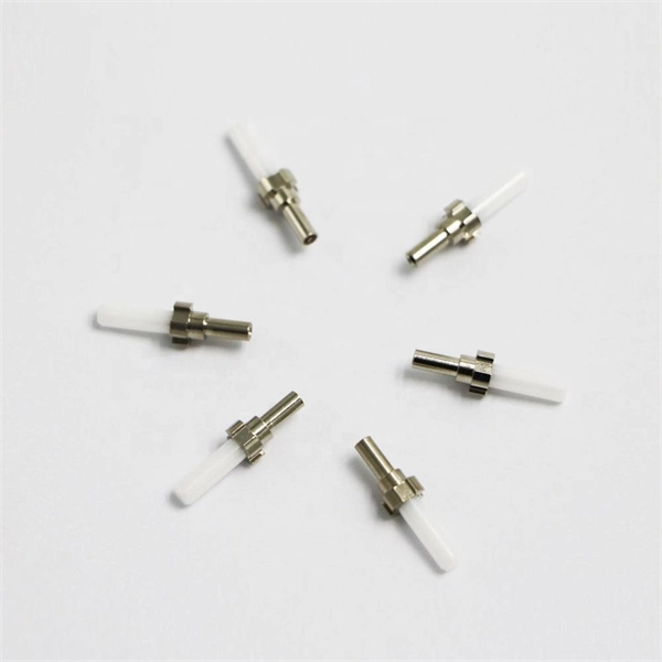
What is a fiber optic cable fused core
Fiber Fusing is a mechanism used to protect fiber optic cables from damage caused by unsafe levels of optical power. This. A fiber optic cable consists of five basic components: the core, the cladding, the coating, the strengthening fibers, and the cable jacket. When searching for a fiber optic cable, we need to pay attention not only to the connectors, such as SC to ST fiber cable, LC to SC fiber patch cable, or SC to. This page explains the basics of a fiber fuse and its function within a fiber optic network. We're all familiar with fuses used in electrical devices, right? A fuse is a safety device that interrupts the flow of current when an electrical circuit is overloaded., at the output end), propagates back towards the light source, melting and destroying the fiber core along its path. Professionals in telecommunications, data centers, and network infrastructure must understand the core functions and why they are fundamental to their fiber optic. However, if there were no cores, fiber optic cables would be useless.
[PDF Version]
-
What to do if the fiber optic cable fusion splice core is misaligned
Check the fusion splicer's alignment system and settings. The root causes typically include: To resolve this, first check the fibre ends. Spending a few extra minutes on calibration often saves significantly more time by preventing failed splices and rework. It is also important to regularly check: These. Place the fibers carefully into the V-grooves of the splicer while aligning the fiber cores along the centerlines so as not to induce splice loss from misalignment of the fiber cores. Ensure proper fibre cleaving techniques, using a high-quality fibre cleaver and following manufacturer guidelines. IEC 61300 standards and best practices from Corning and 3M guide professionals toward consistent performance.
-
Fiber Module Cable Rules
This FOA Technical Bulletin describes recommended procedures for installing and testing cabling networks that use fiber optic cables and related components to carry signals for communications, security, control and similar purposes. The Fiber Optic Association, Inc. The charter of the FOA was to promote professionalism in fiber optics through education, certification, and. The information contained in this manual should serve as a guide to proper handling, installing, testing, and for troubleshooting problems with fiber optic cables. Installation guidelines regarding minimum bend. Recommendations for Fiber Optic Cable Installation Where reels are supplied with protective material fitted over the cable, the protection should remain in place until the cable will be installed. During installation, all curvatures should be smooth. FO-CS JOINT USE CLIMBING SPACE REQUIREMENTS 51. APPENDIX A - COVER SHEET / TOC 52. NEIS® are intended to be referenced in contrac documents for electrical construction ation or liability to users of this publication.
[PDF Version]
-
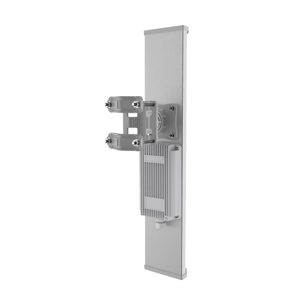
A single optical fiber uses a dual-core optical module
o In optical modules, "core" refers to the light-transmitting channel in the fiber. A 1-core module uses a single fiber core for data transmission, while a 2-core module uses two cores. They are easier to set up and give steady communication. A. Single fiber module also called BiDi transceiver or WDM module. BIDI module only has 1 port, wave filtering through the filter of module, and finished the transmitting of 1310nm optical signal. In today's communication field, single-core optical fibre and dual-core optical fibre are like remarkable stars, the powerful technology behind them and the disruptive impact on the communication industry deserve everyone's attention and discussion.
-
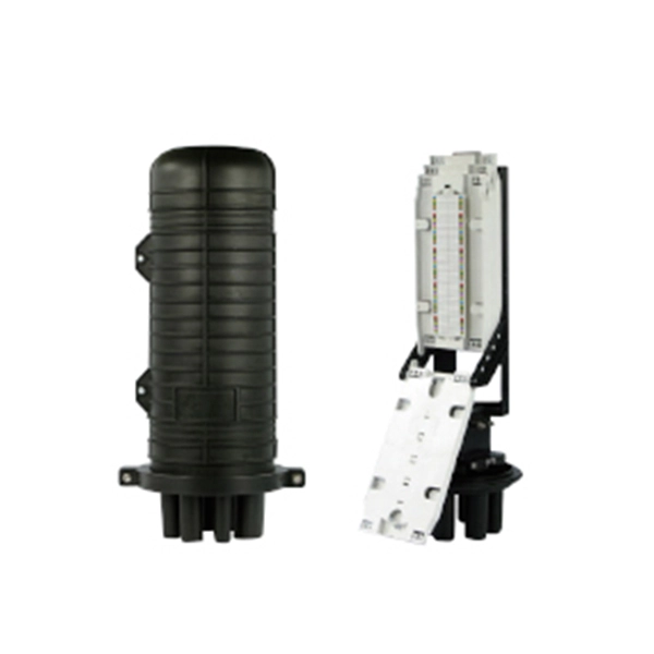
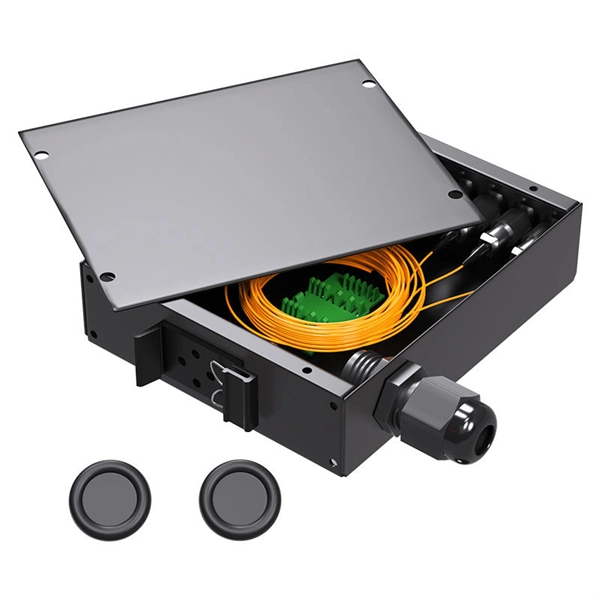
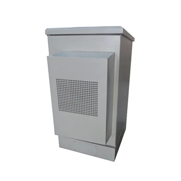
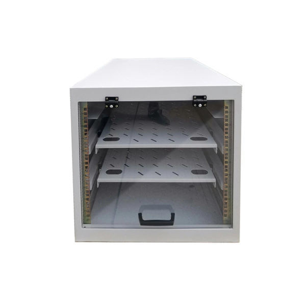
The function of the fiber optic cable protection box
They provide a secure, organized, and stable environment for the sensitive points within a fiber network—splices, connectors, and distribution points—safeguarding them from a multitude of external threats. For any organization deploying or maintaining a fiber network, understanding the role and. Fiber Connection Protection Box is a device designed for fiber optic line terminal connection and protection and is widely used in fiber optic communication systems such as fiber to the home (FTTH), local area network (LAN), and metropolitan area network (MAN). Its main functions can be summarized as follows: 1. Fiber closure protects spliced fibers in backbone and feeder lines, fiber box (or fiber distribution box) organizes and splits fibers in.
-

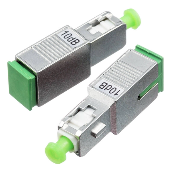
Large reflections occurred during fiber optic cable splicing
Such events are caused by the discontinuity of the fiber's end-face at the connector, resulting in Fresnel reflections and a consequent reduction in transmitted light intensity. When analyzing an OTDR trace, a connector is typically identified as a striking change in the. Executive Summary: A fiber optic pigtail is one of the most commonly specified yet least understood components in structured cabling. Get the wrong connector type, the wrong polish, or skip proper fusion splicing technique—and you're looking at elevated signal loss, increased back reflection, and a. A single imperfect splice can disrupt connectivity for businesses, schools, and homes, causing slow speeds, intermittent outages, and costly downtime. The variations between two optical fibers that. When troubleshooting your fibre optic network and running an OTDR (Optical Time Domain Reflectometer) test, seeing high reflectance can be a real head-scratcher. However, interpreting these traces can be challenging without a structured approach. It can verify splice loss, measure length and find faults. Later, comparisons can be made.
[PDF Version]