-
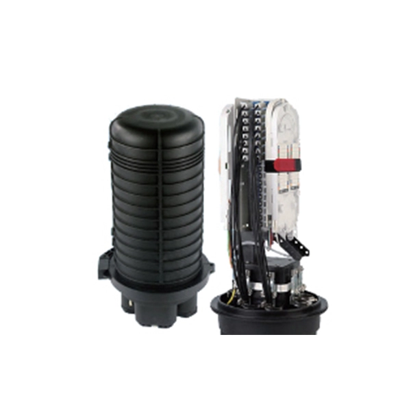
How to coil the fiber optic cable at the end of the optical fiber
For overly long or short fibers, coil them separately at the end. Before fiber coiling, the optical cable and pigtail should be pre-processed, and the optical cable and pigtail should be opened first. The key step is to calculate the reserved length and then splice the optical fiber. The success rate of optical fiber splicing is very important, because once the. Splice fiber optic cables follows these steps: stripping, cleaving, splicing, and coiling. When done right, splicing ensures minimal loss and long-lasting performance. This guide will walk you.
-
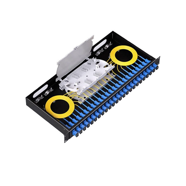
Optical cross-link fiber optic cable tail
A fiber optic pigtail is a pre-installed connector on one end of an optical cable and a length of exposed fiber at the other end. They are the bridge between fiber optic cables in the field and the equipment or patch panels that manage them. Get the wrong connector type, the wrong polish, or skip proper fusion splicing technique—and you're looking at elevated signal loss, increased back reflection, and a. ■ What is a fiber optic pigtail cable? A pigtail fiber indicates a short length of optical fiber cable that has a pigtail connector (for example, SC, FC, ST, LC, etc. ) fitted on one end and the other end undressed (for connection through fusion or splicing) to the main fiber optic cable.
-
Optical fiber cable optical attenuation of more than 30
Attenuation makes signals weaker in fiber optic cables. Check your optical transceiver's specs often. This keeps the signal. Fiber loss, also called fiber optic attenuation or attenuation loss, refers to the loss of signal between input and output. Losses can be introduced by various means such as intrinsic material absorption, scattering, bending, connector loss and more. As depicted below, the decibel, which is used to compare two power levels in dBm, can be defined as the ratio of the optical power P o at the fiber's output to the optical power P i at the fiber's input at a specific. To determine the power budget and power margin needed for fiber-optic connections, you need to understand how signal loss, attenuation, and dispersion affect transmission.
-
European optical fiber cable lines
Berlin, Germany Incab Europe Texas, USA Incab America incabeurope.com incabamerica.comIncab Europe – an independent European enterprise US manufacturing facility — the main production site Building partnerships with European manufacturersIncab America is a relatively new player on the market, but we have managed to prove ourselves as a highly competitive manufacturer here, in the US. We've built our production site from scratch in Arlington, Texas, set the bar in the industry for long-term reliable performance and now we are rapidly developing. I strongly believe that Incab Europe. Business cannot be taught but only be learned through experience. Incab Europe is not just another “kid on the block”, it is the result of vast experience accumulated over many years of hard work of the entire team. When we say that we are a fibre optic cable producer with a guaranteed quality, we really mean it. And we deliver what we promise by. As a legal successor of Emcab, Incab Europe takes on the supply experience and is committed to continue delivering high-quality cables to existing and new customers.
[PDF Version]
-
Fabrication process of optical fiber and cable
The manufacturing sequence can be broken into two broad phases: fiber drawing (producing the raw optical fiber) and cable construction (assembling fibers into a rugged, deployable product). Both phases demand tightly controlled materials, temperatures, and mechanical tolerances. Which are the six main parts of optical fiber? The manufacturing process consists of major steps, including glass deposition, preform fabrication, and fiber drawing, shown schematically below: Each step applies specialized techniques to realize the stringent requirements of optical signal. The manufacturing process of fiber optic cables is a fascinating journey involving cutting-edge technology, precision engineering, and strict quality control. This hair-thin strand of glass or plastic transmits data as pulses of light over long distances with minimal signal loss. This process begins with the creation of a preform, which serves as the foundation for the optical fibers within the cable. The preform. Optical cables are born from ultra-pure glass preforms, drawn into hair-thin fibers, coated for protection, bundled strategically, and encased in durable jackets.
[PDF Version]
-
Can optical fiber be made from a single-layer fiber optic cable
A fiber-optic cable, also known as an optical-fiber cable, is an assembly similar to an electrical cable but containing one or more optical fibers that are used to carry light. The optical fiber elements are typically individually coated with plastic layers and contained in a protective tube suitable for the environment where the cable is used. Different types of cable are used for fiber-optic communication in differen. DesignOptical fiber consists of a and a layer, selected for due to the difference in the between the two. In practical fibers, the cladding is usually coated wit. In September 2012, NTT Japan demonstrated a single fiber cable that was able to transfer 1 per second (10 bits/s) over a distance of 50 kilometers. Although larger cables are available, the highest stra. This list includes both standards-based and real-world technical cable types utilized in fiber-optic infrastructure, telecoms, enterprise, and outdoor applications. • OFC: Optical fiber, conductive• OFN: Optical fibe.
[PDF Version]
-
Budget for underground optical fiber cables for railway communication
Armored fiber optic cables designed for direct burial cost $6-14 per linear foot. Conduit systems add $2-4 per foot but allow future cable additions. These fiber cables connect and transmit real-time data to the ROC for signaling and train control, train movements, traction power substation systems, passenger. Our RDSO-approved Armoured Optical Fiber Cables are engineered for high-performance underground installations in railway signaling and telecom networks. Compliant with IRS:TC 55-2006 Rev. 2 meters (3-4 feet) deep to reduce the likelihood of accidentally being dug up. In extreme cold climates, cables may need to be buried at greater depths where there temperatures are colder and frost penetrates to. The Federal Railroad Administration (FRA) sponsored an evaluation conducted by Transportation Technology Center, Inc. regarding the opportunity and availability to use Fiber Optic Acoustic Detection (FOAD) in the North American railroad industry.
[PDF Version]
-
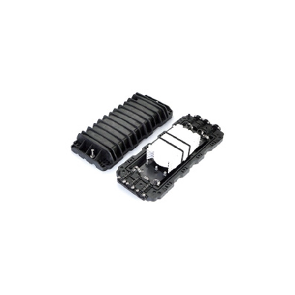
How to open a bundle tube for optical fiber cables
This procedure describes how to access fibers in a bufer tube in a mid-span location with or without slack using the Corning Optical Communications OFT-000 Optical Fiber Access Tool (OFAT) (Figure 1). The instructions in this document explain how to prepare end openings and midspan openings of loose tube fiber optic cable. Be careful not to pull the cable ties too tightly; ⑥Pre-reel the optical fiber, so that the splice point after the connection can be placed in the fixed groove of the optical. The practices contained herein are designed as a guide for use by persons having technical skill at their own discretion and risk. The recommended practices are based on average conditions. Panduit does not guarantee any favorable results or assume any liability in connection with this document.
-
What are the specifications and parameters of multimode optical fiber
Multimode Fiber (MMF) has a core diameter, typically 50–100 micrometers, has ability to transfer multiple modes of light through the fiber core, uses lower-cost electronics (LED, VCSEL) operates at the 850 nm and 1300 nm wavelength and is used for short distance interconnections. Multimode Fiber (MMF) has a core diameter, typically 50–100 micrometers, has ability to transfer multiple modes of light through the fiber core, uses lower-cost electronics (LED, VCSEL) operates at the 850 nm and 1300 nm wavelength and is used for short distance interconnections. Multi-mode optical fiber is a type of optical fiber mostly used for communication over short distances, such as within a building or on a campus. Multi-mode links can be used for data rates up to 800 Gbit/s. In most cases, that number of guided modes is large, e. Figure 1: A single-mode fiber (left) has a core which is very small compared. Multimode fiber works well for short to medium distances, providing scalable capacity and cost-effective deployment for data centers, office buildings, and campuses. Designs under development are listed below.
[PDF Version]
-
Maximum number of optical fiber cores in an optical cable
Multi-core fiber optic cables can contain 3 to 12 cores within a single cable. This significantly increases the data transmission rate, making them ideal for modern, high-demand applications. Multi-core fiber optic cables can serve multiple channels simultaneously to optimize. The number of optical cores in an optical fiber is the total number of equipment interfaces multiplied by 2, plus 10% to 20% of the spare quantity, and if the communication mode of the equipment has serial communication and equipment multiplexing, you can reduce the number of cores. Understanding Fiber Cores: Core: The central glass fiber that transmits light signals. Single-mode: A. The total number of cores for a 1pc fiber patch cable is calculated as the number of branches multiplied by the number of cores per branch (if there are no branches, the number of branches = 1). The following ZR Cable introduces some methods to determine the number of fiber cores.
[PDF Version]
-
Optical Ground of Fiber Optic Communication Line
OPGW (Optical Ground Wire) is a kind of cable that comprises the dual functions of grounding and fiber optic communication. It is increasingly utilized in high-voltage transmission lines as a functional element that both safeguards the power system and allows data sharing across the. An optical ground wire (also known as an OPGW or, in the IEEE standard, an optical fiber composite overhead ground wire) is a type of cable that is used in overhead power lines. Widely used in overhead transmission lines, OPGW plays a crucial role in modern smart grids, telecom integration, and utility infrastructure.