-
Optical fiber cable optical attenuation of more than 30
Attenuation makes signals weaker in fiber optic cables. Check your optical transceiver's specs often. This keeps the signal. Fiber loss, also called fiber optic attenuation or attenuation loss, refers to the loss of signal between input and output. Losses can be introduced by various means such as intrinsic material absorption, scattering, bending, connector loss and more. As depicted below, the decibel, which is used to compare two power levels in dBm, can be defined as the ratio of the optical power P o at the fiber's output to the optical power P i at the fiber's input at a specific. To determine the power budget and power margin needed for fiber-optic connections, you need to understand how signal loss, attenuation, and dispersion affect transmission.
-

Latest Standards for Protection Requirements of Optical Fiber Communication Cables
Follow the latest IEC, TIA, and FOA fiber testing standards in 2025 to ensure your network stays reliable and meets legal and insurance requirements. Use proper testing methods like one-cord referencing, visual inspections, and calibrated equipment to get accurate and. IEC 60794-1-1:2023 applies to optical fibre cables for use with communication equipment and devices employing similar techniques. Electrical properties are specified for optical ground wire (OPGW) and optical phase conductor (OPPC) cables. It specifies that these cables must comply with standards such as ITU-T G. 657, and IEC. We offer full-service OEM and ODM solutions for fiber optic cables, assemblies, and connectivity products — from design and prototyping to global production and logistics. Relevant to Ethernet over fiber, IEEE 802. If you have any questions about IEC copyright or have an enquiry about obtaining additional rights to this publication, please contact the address below or your local IEC member National Committee for further information. The International Electrotechnical Commission (IEC) is the leading global.
[PDF Version]
-
Performance of Optical Fiber Cable Fittings
Fiber coupling can be accomplished by fusion splicing. However, for temporary connections optical connectors are used to produce quick connections and disconnections. Fiber optic cables are essential components in modern data transmission infrastructure. They support high-speed, interference-resistant communication and are particularly effective in applications that require high bandwidth, low latency, and strong signal integrity. Combined with easy use, cleaning and maintenance. Tested for harsh and extreme environments (Norm IEC 61753-1 Cat. Dig-ups dominate! Cablers have very little influence on the majority of causes of cable field failures. While a small percentage, we can examine the “intrinsic” cable failures and what is done to prevent. Laboratory accelerated aging environments have long been used as a measure to predict field performance of optical fiber and cables' ability to withstand harsh environments. To this end, actual field.
[PDF Version]
-
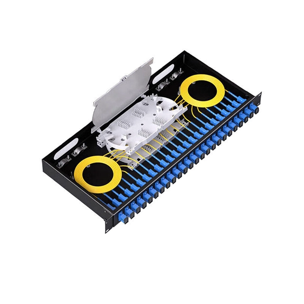
How to fix the optical cable in a Huijue fiber optic ODF box
Excavate the cable at the break point and use a fiber optic cutter to remove the damaged section. Use a high-precision fiber cleaver to prepare the fiber ends for. While a cut or damaged fiber optic cable can temporarily take your network down, it is possible to quickly fix the cable with the right tools. When fiber cables sustain damage, specialized repair techniques help restore connectivity and maintain data integrity. When it comes to ensuring nice network experiences for users, the condition of a fiber. As we move deeper into 2025, with global fiber deployments accelerating at a 10. Locates fiber breaks and measures signal loss before and after. Here are the steps to repair a cut fiber cable.
-
Plug an optical module into both ends of the optical fiber
Do not insert the optical module with optical fibers directly into an optical interface. From enterprise access networks to large-scale data centers, SFP modules allow network. In high-speed data networks, the seamless integration of fiber optic cables with SFP (Small Form-Factor Pluggable) modules is critical for reliable signal transmission. However, with a bit of guidance, the process is straightforward. This article will walk you through the necessary steps to ensure a successful connection. This optical transceiver tutorial will introduce how to install SFP module, how to remove SFP module, and give some insights on the operation precautions.
-
Cable and Optical Fiber Laying Methods
This comprehensive guide examines all major fiber installation methods, from underground trenching to submarine cable laying, providing technical insights drawn from industry best practices and real-world deployment experiences. We should always consider the restrictions established by different administrations related to this matter. Starting with site surveys and permissions, to installing fiber optic cable and emphasizing the process as a key stage in mastering fiber optic installation, to the careful handling of cables and high-stakes splicing, each stage is critical. Whether you're a technician, a network planner, or simply curious about fiber optic technology, this article will. This comprehensive guide explores the essential processes and best practices for underground fiber optic cable installation, helping business decision-makers understand the investment required to upgrade their telecommunications infrastructure.
[PDF Version]
-
How many cores should be selected for optical fiber cables
For most setups, cables with 12, 24, or 48 cores are common choices, ensuring compatibility with modern equipment and ease of management. Fiber cores are the heart of fiber optic cables, transmitting light signals that carry data. Made from either high-quality glass or plastic, the core plays a critical role in determining the cable's performance. The total number of cores for a 1pc fiber patch cable is calculated as the number of. One key factor is the number of cores, which impacts how much data you can transmit. Single-mode: A. The number of optical cores in an optical fiber is the total number of equipment interfaces multiplied by 2, plus 10% to 20% of the spare quantity, and if the communication mode of the equipment has serial communication and equipment multiplexing, you can reduce the number of cores.
-
How to disconnect the fiber optic cable from a 40G optical module
To remove the cable, follow these steps: Attach an ESD-preventive wrist strap and follow its instructions for use. When pulling a cable from a transceiver, grip the body of the connector. If the cable does not remove easily, ensure that any latch present on the cable has been released before continuing. Whether you're upgrading bandwidth, replacing a faulty unit, or reconfiguring your topology, knowing. The modules are hot-swappable input/output (I/O) devices that connect the system's module port electrical circuitry with either a copper or a fiber-optic network. This document contains these sections: The 40-Gigabit QSFP+ transceiver module is a hot-swappable, parallel fiber-optical module with. Note: Before removing the dust plugs and making any optical connections, please remember the following guidelines.
-
Applications of ADSS optical fiber cables
AFL-ADSS® (All-Dielectric Self-Supporting) fiber optic cable is a non-metallic cable which supports its own weight without the use of lashing wires or messenger cables, typically installed in overhead applications along power distribution or transmission rights-of-way. In the realm of aerial fiber optic infrastructure—where cables must withstand harsh weather, high voltages, and mechanical stress— ADSS (All Dielectric Self-Supporting) fiber optic cables stand out as a game-changer. The self-supporting idea is literal here. The result is that they can be hung in a straight line between poles or towers with no additional metallic. One such innovation is the ADSS cable, a fiber optic solution designed to meet the demands of modern networking while providing exceptional performance and reliability.
-
How to apply 8-core optical fiber cable to circuits
Learn how to splice fiber optic cable using fusion splicing with this complete step-by-step guide. Includes tools, best practices, loss standards (ITU-T G. 652), cost analysis, and FAQs for network engineers and installers. Regardless of the type of fiber network you're deploying, be it for telecom, enterprise data centers, or smart city infrastructure, fusion splicing provides the benefits of. Imm(branch cord)/2. Imm (main cord) Material Stainless Steel Color Silvery White UL94 V-0 (*Burning stops within 10 seconds on a veritcal specimen, no drips of flaming particles. ) *Exact product code is subject to the cable length. Specifications are correct at time of printing and subject. This article will guide you through the necessary tools, materials, and methods on how to connect fiber optic cables effectively, ensuring you achieve optimal performance from your fiber optic network. Have a network installation project? Fiber Optic Cables: The primary medium for your connections. The document also covers applications notes including the use of coupling coils and hardware recommendations for aerial installations. Question? Call 1-800-669-0808.
[PDF Version]
-
Long-distance optical fiber communication
This paper discusses the fundamental principles of optical fi ber communication, key technologies such as lasers, optical amplifi ers, and photodetectors, and recent advancements in improving effi ciency, speed, and distance. Utilizing light waves to transmit information, this technology offers signifi cant advantages, including high bandwidth, low attenuation, and minimal interference compared. Basic configuration of an optical fiber communications system Compared to conventional metallic cables, optical fiber provides an advantage of low loss (~ 0. 2dB/km) and wide bandwidth (several hundred MHz to THz) to enable long-distance, high-capacity communication. Additionally, optical fiber is. In the demonstration experiment, we demonstrated a high-capacity transmission of 455 terabits per second over a transmission distance of 53. 5km by applying large-scale MIMO 1 signal processing technology in a terrestrial field environment in which a 12-core fiber with the same diameter as existing.
[PDF Version]