-
What is the relay protection time difference
The IEC standard for relay coordination recommends time grading between relays based on fault current magnitude and operating characteristics. For overcurrent protection, a minimum time margin of 0. 5 seconds is often maintained between primary and backup relays. The principle is to grade the operating times of the relays in such a way that the relay closest to the fault spot operates first. In order for the relay to operate, it needs to be energized. This energy can be provided by battery sets (mostly) or by the monitored circuit itself. In which case you use any of them. Are there any benefits of using one. A protection relay is a crucial component of electrical systems that safeguard infrastructure, employees, and equipment from electric problems and malfunctions. The relay settings that are selected are often a compromise in order to cope with both overload and. In electrical engineering, a protective relay is a relay device designed to trip a circuit breaker when a fault is detected.
[PDF Version]
-
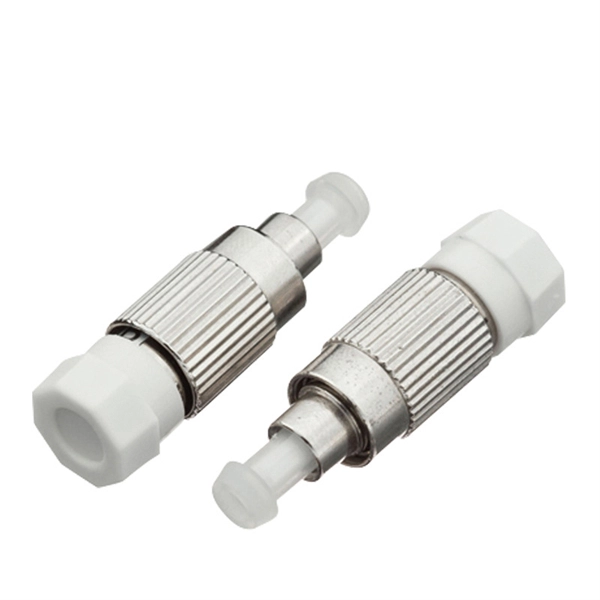
Is an optical converter an optical module
An optical module is a typically hot-pluggable optical transceiver used in high-bandwidth data communications applications. Optical modules typically have an electrical interface on the side that connects to the inside of the system and an optical interface on the side that connects to the outside world through a fiber optic cable. The form factor and electrical interface are often specified by an interested group using a (MSA). Optical modules can either plug into a front pa.
-
Fiber optic communication within the same time period
The transmission distance of a fiber-optic communication system has traditionally been limited by fiber attenuation and by fiber distortion. By using optoelectronic repeaters, these problems have been eliminated.OverviewFiber-optic communication is a form of for from one place to another by sending pulses of or through an. The light is a form of. First developed in the 1970s, fiber-optics have revolutionized the industry and have played a major role in the advent of the. Because of its advantages over electrical transmission, optical fiber. is used by telecommunications companies to transmit telephone signals, Internet communication and cable television signals. It is also used in other industries, including medical, defense, governmen.
-
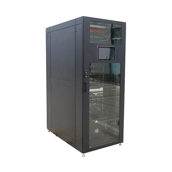
Price of the Burundi Dynamic Brillouin Optical Time Domain Reflectometer
A Brillouin Optical Time Domain Reflectometer can cost anywhere from $50,000 to $200,000, depending on the specifications and features. In contrast to simple optical loss test sets (OLTS) which measure only the total. The Naval Undersea Warfare Center Division, Newport (NUWCDIVNPT) is seeking a firm fixed price purchase order for one Brillouin Optical Time Domain Reflectometer (BOTDR), one travel case, and one 19" rack mount kit. The BOTDR should have the capability to measure strain and temperature in various. Guangdong Bailing Optoelectronics Technology Co. These are some of the reflections using a comparative TDR. Installers regularly. The OZ Optics' ForeSight™ family of fiber optic Brillouin distributed strain and temperature sensors (DSTS) utilizes Brillouin scattering to provide sophisticated optical sensor systems for distributed sensing.
[PDF Version]
-
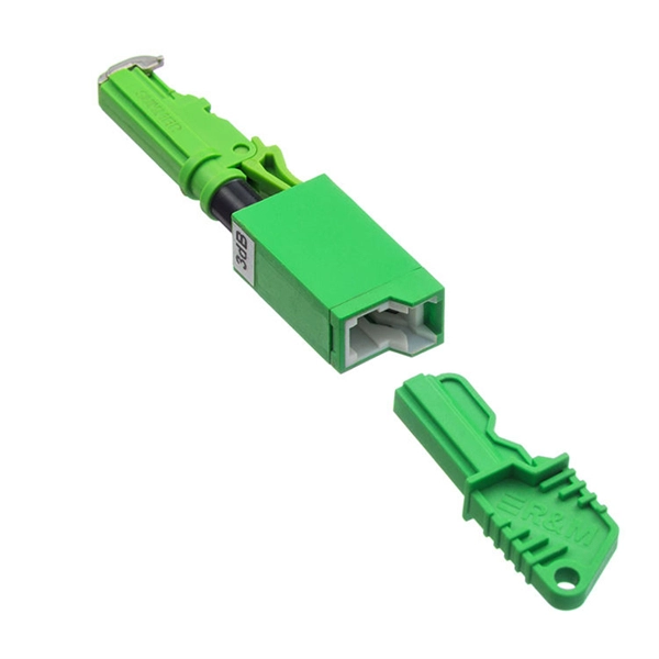
Fiber Optic Fusion Splicer Calibration Time
Next the splicer prompts to confirm that a Quick Optimization or Arc Calibration has been performed before splicing the fiber. Fusion splicing is the process of fusing or welding two fibers together usually by an electric arc. The guide provides the complete workflow, covering safety precautions, tool selection, fiber preparation, fusion operation, quality control, and. Fusion splicers are essential for creating low-loss, high-performance fiber optic connections in telecom, FTTH, and data center applications. Top-rated models. It is recommended practice to keep fiber optic test equipment calibrated in measurement to ensure fast troubleshooting when locating network failures or when providing optical attenuation or optical cable length certification results. These records are required to close out a project and receive. At FiberOptic Resale our technicians have the experience and knowledge to clean and calibrate a broad range of fusion splicers and cleavers. Please follow all warnings and cautions for your safety and the protection of the equipment.
[PDF Version]
-
Malaysia Delivery Time for 40G Optical Receiver
Delivery time for East Malaysia (8-10 Business days) as the location of the stock hub is in Penang. Our delivery. What Does the status means? What Does the status means? Track your parcel's journey from start to finish with GDEX's easy-to-use parcel tracking service. Track shipping to be in control every step of the way. Please ask for the stock availability first to avoid any disappointment. Specifications Features 40G QSFP+ Optical Stack Cable (included both side transceivers), 5. The DSC-R401HG is a linear and versatile PIN + transimpedance amplifier suited for a variety of digital and analog applications. The R401HG offers a linear response to > +3 dBm optical input, 600mVp-p of linear output voltage, 20 GHz of RF bandwidth and a conversion gain of 160 V/W.
-
Telecom fiber optic cable repair time
However, the majority of fiber repairs can generally be completed within a 2-4 hour window after technicians arrive. Factors affecting repair time include the necessity for 24/7 service availability. Typical repair timelines can vary; representatives from maintenance companies noted that a severed line might be fully operational again within four hours once onsite work. Fiber optic cable repair encompasses the diagnostic, splicing, and restoration procedures applied to damaged or degraded optical fiber infrastructure across telecommunications, enterprise, and utility networks. Common issues stem from physical, environmental, and human factors, often leading to signal loss, increased attenuation, or complete outages. Locates fiber breaks and measures signal loss before and after. But i switched to them from Spectrum for their speed and affordability, If this were spectrum, they at least would've sent someone out here tonight or tomorrow to fix the issue.
[PDF Version]
-
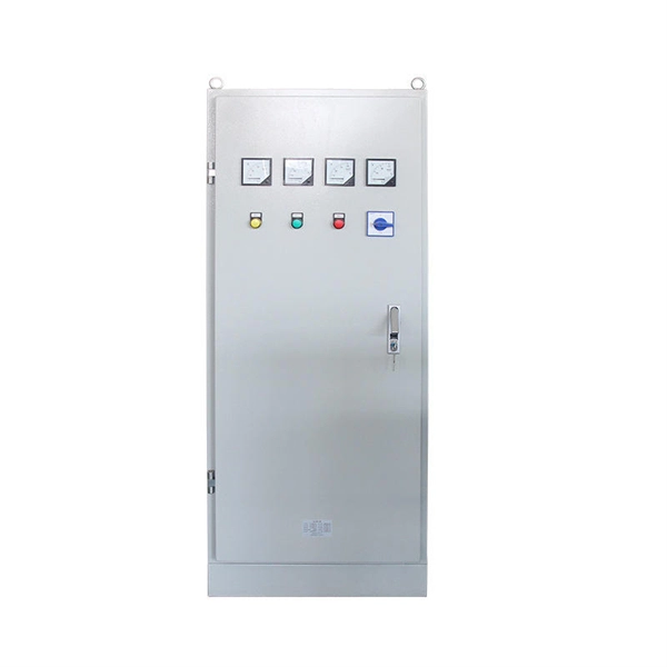
35kV busbar protection time
Operating time of any tripping protection relays must be added to this time, however an overall tripping time of less than two cycles can be accomplished. With high-speed circuit breakers, total fault clearance may be obtained in roughly 0. Common methods of protecting busbars include overcurrent-based interlocking schemes, overcurrent-based differential protection, high-impedance differential protection, and percentage differential protection. Interlocking and overcurrent differential protection can be implemented with any suitable. This specification applies to three-phase, [select #] - way [select # -source, select # -tap], 50-60 Hz, fully dead front, sectionalizing underground distribution switchgear; with maximum main bus rating of [select: 200 or 600] amperes continuous current and maximum tap rating of [select: 200 or. In principle, busbar protection is needed when the system protection does not protect the busbars, or when, in order to keep power system stability, high-speed short circuit current clearance is needed. Unit busbar protection meets these requirements. Also, in the case busbars sections are. A FAULT IN A BAY BETWEEN A CB AND A CT.
[PDF Version]
-
How to measure the protection action time of relay protection instruments
We provide guidance regarding test signals, propose a number of ways to measure and compare relay performance, discuss the issue of type testing, and review requirements for transient simulation and playback tools for testing ultra-high-speed line protective relays. Action time, as an important indicator to measure the response speed of relay protection devices, reflects the duration from the input of fault signals to the output of actions of the protection devices. The setup serves to simulate faults and create transient waveforms. Abnormalities are detected of the protection relay with the help of the following general tests: This basic test determines the time that the relay takes to respond when detecting these faults. Then, set the tester parameters, including the operating voltage, operating current, and the phase angle between voltage and current. We review traditional performance measures, such as transient overreach for distance zone 1, and formalize other measures, such as operating time and dependability. Ensure protection systems operate correctly.
[PDF Version]