-
11 Wavelength Division Multiplexer Principle
Wavelength division multiplexing (WDM) is a technique of multiplexing multiple optical carrier signals through a single optical fiber channel by varying the wavelengths of laser lights. WDM allows communication in both the directions in the fiber cable. This guide delves into the principles, types, applications, and future trends of WDM.
-
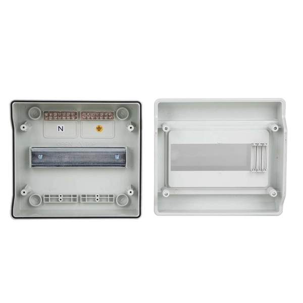
What is a distribution box enclosure
A distribution box, or DB box, is a circuit breaker enclosure. It is a vital part and central hub of any electrical system. The hub distributes electrical power from a single input source to various circuits throughout a building. It typically contains essential components such as circuit breakers, surge protectors. Distribution boxes, or electrical junction boxes as they are sometimes called, play a vital role in electrical systems. The boxes also store protective equipment devices. Electrical systems power our homes, offices, and industrial facilities, but behind every reliable electrical setup lies a crucial component that often goes unnoticed: the distribution box.
-
Power Cable Tray Installation Steps
Step-1: Confirm the actual layout, dimensions & mounting height of cable trays & conduits. Step-3: Coordinate with other trades to prevent interference during installation. Article Summary: A compliant cable tray installation requires a thorough understanding of NEC Article 392, proper structural support, and precise installation techniques. The Cable Tray ng standards, performance standards, test standards and application in this document have been tested extens ompetent professional en completely installed, without damage either to conductors or. Here is a step-by-step guide on how to install a standard metal cable tray system (e. This guide covers copper and aluminum conductors from No. 14 AWG though 1000 kcmil, insulated for operation from 600 volts though 35 kilovolts.
-
Generator Distribution Box Configuration
In this guide, we'll break down everything you need to know to install a distribution box correctly and confidently. Choose the right box based on environment (indoor/outdoor), load capacity, and durability. Check for proper IP/NEMA ratings and material quality. To safely and efficiently distribute power from a portable generator, a portable generator connection box is an essential accessory. Single-phase units are suited for smaller applications, while three-phase units handle larger loads, making them ideal for construction. The Generator Connection Cabinet (GCC) provides a connection point only for a portable generator or load bank. A consulting electrical engineer can help determine the optimal configuration to. NFPA 70: National Electrical Code Article 700 specifies the requirements to install emergency power systems such as lighting when power from the normal source is interrupted. Ensure safe placement: install in.
[PDF Version]
-
Installation steps for plastic cable trays
Step-1: Confirm the actual layout, dimensions & mounting height of cable trays & conduits. Step-3: Coordinate with other trades to prevent interference during installation. This guide breaks down the process step by step. Mark the cable tray route based on your electrical cable tray design and site. Article Summary: A compliant cable tray installation requires a thorough understanding of NEC Article 392, proper structural support, and precise installation techniques. In order to get it right, installers are supposed to adhere to a plan that ensures that wires are kept cool and the building is stable. The beginning of success is to review the Bill of Quantities (BOQ) so that. This method statement describes a detailed procedure for properly installing cable trays and conduits for the Feeder System. It ensures that all installation activities follow authorized plans, specifications, and standards.
[PDF Version]
-
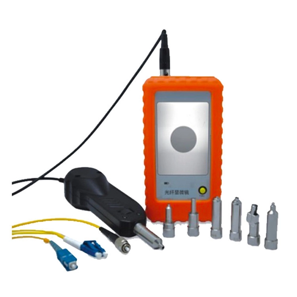
Steps for troubleshooting optical modules
Ensure module is fully seated, check optical power levels (Tx & Rx), replace suspect patch cord. Vendor incompatibility, outdated device firmware, incorrect module type for slot. Consult vendor compatibility list, upgrade device firmware, confirm module form-factor (SFP . Customers in the use of optical modules will more or less encounter a variety of failure problems, such as optical module model selection is correct, the use of jumper is correct and some common problems, customers have the ability to judge and have a clear solution, but for some of the use of. Based on typical issues encountered with optical modules in daily switch applications, this document summarizes basic troubleshooting steps for resolving common faults: 1. However, during installation and daily operation, various issues may arise. Therefore, understanding common optical module. The Ultimate Guide to Principles, Types, and Troubleshooting Optical Modules (also known as Optical Transceivers) are critical components in fiber optic communication systems. It is important to understand how to.
[PDF Version]
-
Steps for sealing vertical shaft cable trays
Spring knot is used to connect cable tray or trunking to channel. Approved and correct fittings are used. Installed containments are free of damages. maintain spacing or to keep cables in place when the tray is ect the minimum bend ra-dius for cables as they exit the bottom of the cable tray. A rung spacing of 6 to 9 inches (150 to 230 mm) is preferable when the cable tray cont d for instrumentation and control applications that require. What materials are available to make a watertight penetration through the top of a concrete pull box for a vertical run of cable tray? In practice, is it preferable to use PVC conduit with rubber pipe sleeves? My preference is to exit horizontally and use a ninety to go vertical. The Cable Tray system is installed in electrical rooms, plant rooms, and service. Tools and equipment needed for cable tray support installation should be in good condition and must be checked by Supervisor / Safety Engineer prior to use in the construction area.
[PDF Version]
-
Steps for laying out cable tray bends
This guide explains how to make 90° bends, vertical bends, tees, and offsets in wire mesh cable trays safely and professionally. Horizontal 90° Bend (Flat Bend) 2. But before you lay the first tray or clamp down a single cable, you need a solid plan. This guide breaks down the process step by step. When a wire cable tray is cut, the fact that a. Installing a cable tray system requires careful planning to ensure it can support the weight of the cables and adheres to electrical safety codes. Cable tray system design shall comply with National Electrical Code® (NEC® ) Article 392, NEMA VE 1, and NEMA FG 1 and follow safe work practices a described in NFPA 70E. Further, it is recommended that installers follow all guidelines and best practices found in NEMA VE 2. Students trading aid on how best to put an internal 90 degrees bend in steel cable tray.
[PDF Version]
-
Steps for Short Circuit Calculation in Relay Protection
Voltage levels, transformer ratings and impedances, line lengths and impedances, generator/motor data. Select fault location Choose busbars or nodes where faults will be studied. Apply IEC. A short circuit occurs when an unintended low-impedance path forms between: Physical Causes: Critical Applications: ⚠️ Safety Critical: Incorrect fault current calculations can result in explosive equipment failures, arc flash incidents causing severe burns, and system-wide cascading failures. The principle is to grade the operating times of the relays in such a way that. The scope of study involves calculating the settings for protective relays to achieve selectivity during faults ocurring in the electrical network for the 13. In OC relays the coordination is based on the relay time-current characteristics of instantaneous and/or time delay units. Instantaneous units should be set so they. As of this update, Service Disconnect Switches, Surge Protective Devices, Switchboards, Switchgear, and Panelboards, Industrial Control Panels, Motor Controllers, Elevators, Industrial Machinery, and Transfer Equipment are all required to have short-circuit current ratings.
[PDF Version]