-
What are the testing methods for pigtail splicing
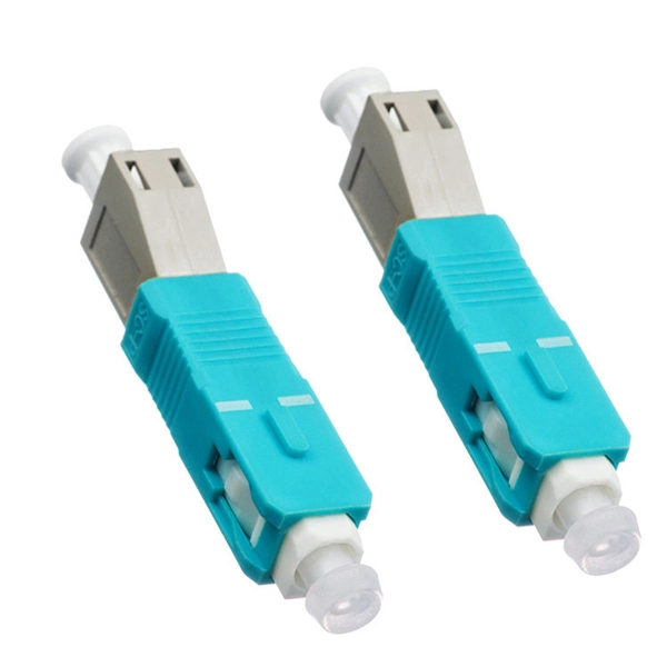
To test fibre splicer quality, begin by inspecting cleave angles and fibre cleanliness. Next, confirm arc calibration and alignment using the splicer's splice loss estimation. Follow up with OTDR or ILM testing to validate results. This guide covers everything: what fiber optic pigtails are, how they differ from patch cords, which connector and polish type to specify, how to choose between mechanical and fusion splicing, and the real-world applications where pigtails are the right call. The Contractor must utilize the correct equipment and testing techniques to gain acceptance, or the work cannot be approved. Either joining method must have three primary characteristics. The most efficient way to terminate a fiber run is by using a pigtail.
-
10kV Busbar Voltage Testing Standard
IEC 61439 is a standard developed by the International Electrotechnical Commission (IEC) that covers design verification for low-voltage electrical products and assemblies. The IEC 61439. 7 cycles of 24 h each to salt mist test according to IEC 60068-2-11; (Test Ka: Salt mist), at a temperature of (35 ± 2) °C. The test shall be carried out according to IEC 60068-2-2 Test Bb, at a temperature of 70 °C, with natural air circulation, for a duration of 168 h (7 days) and with a recovery. ULTRUS™ helps companies work smarter and win more with powerful software to manage regulatory, supply chain and sustainability challenges. Consistent performance benchmarking testing capabilities for professional PC users. Award-winning software and advisory services for ESG management and. The purpose of this method is to verify the functionalities of a Metal Enclosed Busb ar. How do you check and maintain busbars? What are the faults of busbar? What is bus bar in DB? For complete safety instructions and precautions, always refer to the test equipment instruction manual.
[PDF Version]
-
Total loss during optical cable testing
Visual inspection identifies contamination, scratches, cracks, and endface defects that directly affect optical performance. Insertion loss testing measures the total optical loss of a fiber cable or. To be able to judge whether a fiber optic cable plant is good, one does a insertion loss test with a light source and power meter and compares that to an estimate of what is a reasonable loss for that cable plant. The estimate, called a "loss budget" is calculated using typical component losses for. At TREND Networks, we are frequently asked how much loss is allowed when conducting testing on fibre optic cabling. Unfortunately, it is not a simple answer and depends on several factors. So how do you determine acceptable loss? When testing fibre optic cabling, determining acceptable loss is. required. patchcords, with negligible fiber loss, the measured loss may be considered the loss of the connector mated to the reference connector.
[PDF Version]
-
Microcomputer Testing of Relay Protection
For testing high-voltage microcomputer protection devices, it is recommended to use a microcomputer relay protection tester capable of simultaneously outputting three-phase voltage and three-phase current, and equipped with timing function for digital inputs. Meet all test requirements on site. It can test not only various traditional relays and protection devices, but also various modern microcomputer protections, especially for transformer differential protection and. Protective Relay Test Set, Relay Tester, Secondary Current Injection Test Kit, Microcomputer Protection Testing, 3-Phase Relay Tester Discover why selecting the right Protective Relay Test Set is critical for microcomputer protection verification. In this paper, the characteristics of the equipment itself and the external environment are comprehensively considered, and.
[PDF Version]
-
Relay Protection Inspection and Acceptance
This guide explores the different types of protection relays and their testing procedures, with a focus on tools like secondary injection test sets and three-phase relay test sets. To properly test relays, understanding their classification by design and application is. The testing and verification of relay protection devices can be divided into four groups: Type tests are needed to prove that a protection relay meets the claimed specification and follows all relevant standards. These are not repeated unless incorrect operation occurs. Although failure of a protective relay system may have severe local or regional impacts, most protective relay systems are not required to operate to prove they are in working order.
-
Building Optical Receiver Testing Basis
Optical Power Meters: Measure the optical power received. Bit Error Rate Testers (BERT): Evaluate data integrity and error rates. Optical Spectrum Analyzers: Check the spectral characteristics of the. Use 25+ X-Series applications to analyze, demodulate, and troubleshoot signals across wireless, aerospace/defense, EMI, and phase noise. With extra memory and storage, these enhanced NPBs run Keysight's AI security and performance monitoring software and AI stack. Achieve fast, accurate board-level. In case of 400G may need to use fiber with min/max zero dispersion. It's generally pretty simple to nd the gross problems, such as oscillation, power supply crap getting into the signal, tilted pulse tops due to high- or low-frequency peaking and rollo, or bad. Optical receivers are essential components in fiber-optic communication systems. This agreement defines not only the performance, size, efficiency standards, but also the.
[PDF Version]
-
Correct Method for Testing Optical Power Meter Readings
Use an optical power meter for this task. You use it to measure the strength of light signals in fiber optic cables. The basic process is straightforward: turn the meter on, set it to the correct wavelength, clean your connectors, plug in, and read the. FOA "Quickstart Guides" are short, simple guides to basic fiber optic tests.
-
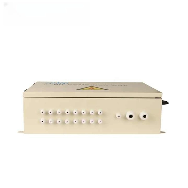
Assembly and Installation of Small Distribution Boxes
The steps to install a small distribution box include selecting a suitable location, installing the base, placing the distribution box, connecting the wires, and checking for acceptance. Warm reminder: Do not disassemble or modify without experience and professionals. It takes the incoming power and safely distributes it to different circuits throughout your building. We focus on workflow efficiency, assembly er. Select location Before. In modern electrical systems, cable distribution boxes (also known as electrical distribution boxes or distribution boxes) play a crucial role as the key hub for managing, distributing, and protecting circuits.