-
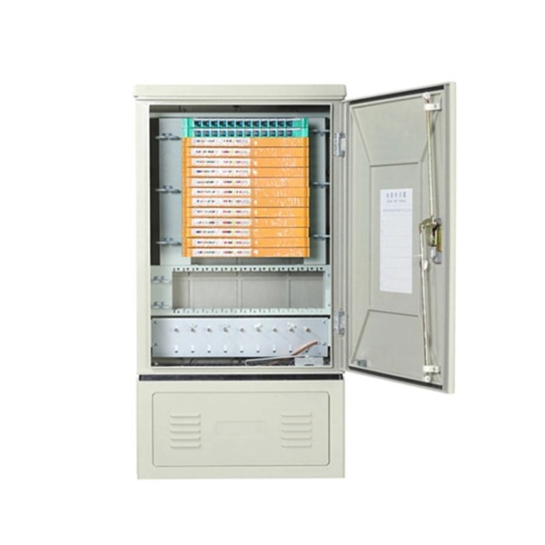
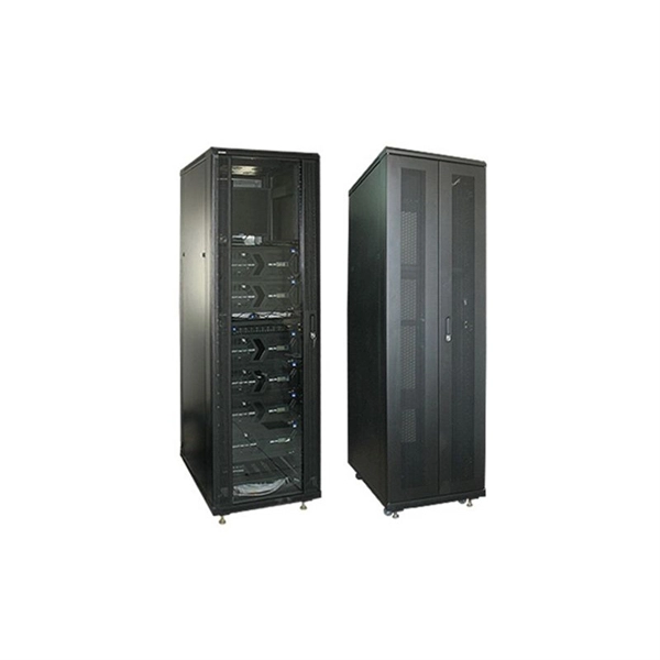
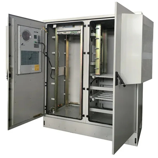
What are the components of high and low voltage complete sets of equipment
High and low voltage complete sets of electrical equipment refers to the combination of electrical equipment components including circuit breakers, isolating switches, load switches, fuses, voltage transformers, current transformers, lightning arresters and other electrical. High and low voltage complete sets of electrical equipment refers to the combination of electrical equipment components including circuit breakers, isolating switches, load switches, fuses, voltage transformers, current transformers, lightning arresters and other electrical. High voltage and low voltage complete sets occupy a significant place in modern electrical engineering as they are responsible for safe, secure, and efficient power distribution to all types of industries. They are known as complete switchgear assemblies because they integrate inside them such. Electrical switchgear is a complete set of equipment composed of circuit breakers and isolation switches. Like switchgear, circuit breakers, load switches are in this category; control equipment, contactors, relays; protection equipment including fuses, over-voltage protector; and.
[PDF Version]
-
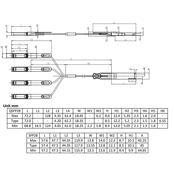
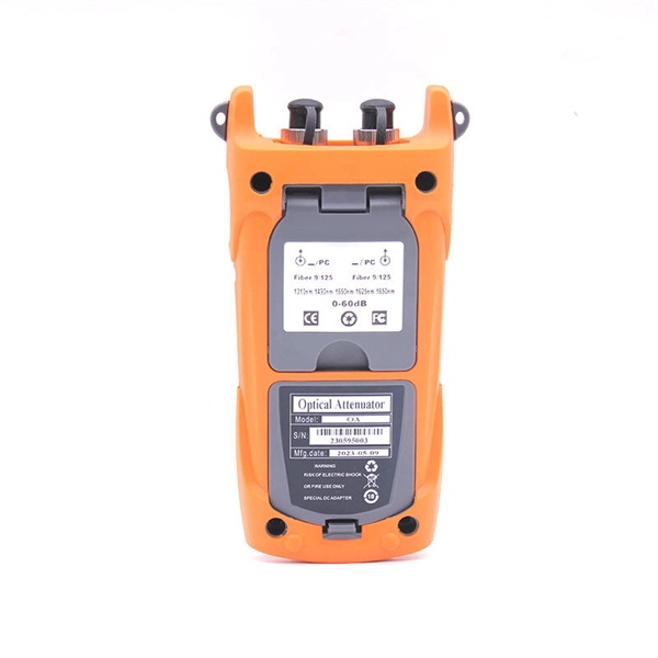
Optical module test power not adjusted too low
What does it mean if the transmitted power is too low? Low transmitted power can mean the connectors are dirty. Clean the connectors, check the module, and look at the fiber. If it still does not. Stable optical power is the foundation of every high-capacity optical transport system. Even minor deviations—whether too high, too low, or unstable—can impact signal integrity, trigger service alarms, or interrupt traffic on DWDM, OTN, or long-haul optical line systems. Because optical networks. The article Digital Diagnostic Function (DDM) For Optical Modules describes that DDM function can be used for real-time monitoring and fault location of the module's working status, in which the optical module's transmitting optical power and receiving optical power are the key parameters for. To test transmitted power in sfp optical modules, you use an optical power meter to get exact results. Many sfp modules also have DOM/DDM, which lets you see digital diagnostic monitoring data on network equipment. Built into modern SFP/SFP+/ SFP28 /QSFP family modules and standardized by SFF-8472, DDM/DOM exposes real-time values for the module's temperature, supply.
[PDF Version]
-
Commercial Value of Hollow-Core Optical Fiber
The Global Hollow Core Optical Fiber (HCOF) Market is anticipated to witness robust growth at a CAGR of 17. 74 billion by 2030 from USD 1. 42 billion in 2024, fueled by ultra-fast connectivity, 5G deployment, optical networking, low-latency transmission, telecom innovation, and. Hollow by Material Type (Plastic, Glass), By End User (Aerospace and Defense, Telecommunication, Information Technology, Medical, Others), and By Region Forecast to 2034 The Hollow Core Optical Fibre Market size was estimated at USD 184. I need the full data tables, segment breakdown, and competitive landscape for detailed regional analysis and revenue estimates. Global Outlook – By Type Of Fiber (Photonic Bandgap Fibers, Anti-Resonant Fibers, Other Specialized Hollow-Core Fibers), By Material (Silica, Polymer, Other Materials), By Manufacturing Process (Extrusion Process, Draw Tower Process, Lasing And Sintering Methods, Other Advanced Manufacturing. The global hollow core optical fiber market size was valued at $190.
[PDF Version]
-
OTDR Fiber Optic Tester Low Light
An OTDR is a powerful tool that helps technicians and engineers assess the health of fiber optic cables. OTDRs inject high-powered light pulses into the fiber using specialized laser diodes. As these light pul.
-
How to measure the optical attenuation value of fiber optic patch cords
The primary tool for measuring attenuation in installed fiber is an Optical Time Domain Reflectometer, or OTDR. The most fundamental parameter for optical fiber is geometry, since the dimensions of the fiber determine its ability to be spliced and terminated to other fibers. The core diameter, cladding diameter and concentricity are the most important factors on how well one can connect or splice two fibers. In this tutorial, we'll take a look at the.
-
Loss value of new optical cable 1310
Used to suggest a default attenuation value. Route length between active equipment. Usually higher loss than fusion splices. Include patch. At Aeliya Marine Tech, we strive to provide efficient and reliable shipping services to our customers worldwide. Please read the following information regarding our shipping policy: We offer various shipping options for each country, and the methods and costs are clearly indicated on all. Calculate link or channel loss and determine the supported applications and max lengths for the configuration. You can also select components to configure connections below. QuestTel shall have no liability for any error or damage of any kind resulting from the use of this document. Connector and Splice Losses: Every connector or splice in a fiber optic network introduces additional. This document outlines the specifications for a single-mode optical fiber and cable designed for use around the 1310 nm zero-dispersion wavelength, suitable for both the 1310 nm and 1550 nm regions, and compatible with analogue and digital transmission. It details the fiber's geometrical, optical.
[PDF Version]
-
Maximum allowable voltage drop value of 10kV busbar
The formula used is IMAX = (I * 100) / (100 + VD), where I is the busbar current rating and VD is the allowable voltage drop. Typical values for LV installations are given below in Figure G27. 1) These voltage-drop limits refer to normal. Instant voltage drop limits calculator: NEC and IEC compliant, auto-applies 3%/5% rules for lighting, feeders. Enter nominal voltage and optional measured drop; get pass/fail, max allowable volts, length helper instantly. Design by percent limits: compute max length, minimum size or actual drop. Voltage drop is the reduction in voltage along a bus bar due to its resistance. This standard defines the design verification, test requirements, and thermal performance of the assemblies.
-
Value Assessment Report for Explosion-proof Distribution Boxes
This report is a detailed and comprehensive analysis for global Explosion-Proof Distribution Box market. The global market for Explosion-Proof Distribution Box was valued at US$ million in the year 2024 and is projected to reach a revised size of US$ million by 2031, growing at a CAGR of %during the forecast period. 5 billion by 2034, registering a CAGR of 7.
-
Inspection after changing the setting value of the relay protection device
The purpose is to inspect the insulation between the relay terminals and the ground. Use a megohmmeter (such as 500V DC). Check wiring & . Protection Relay Testing is the procedure used to verify the performance, accuracy, timing, and operational condition of protective relays installed in electrical systems. These relays monitor electrical parameters such as current, voltage, frequency, impedance, and phase angle. But when it's needed, it has to perform. Servicing protective relays per manufacturer and NETA recommendations ensures they work properly to prevent injury or extensive damage to your plant during. Low Tension (LT) protection relays protect electrical systems by finding abnormal conditions such as Ground faults.
-
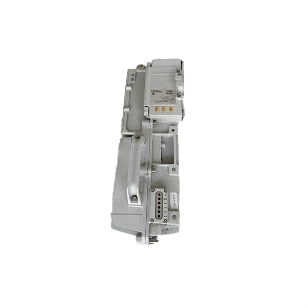
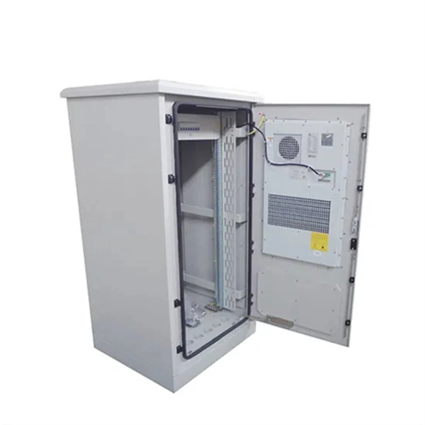
Outdoor integrated power supply with low loss for cloud computing applications
While designing a power supply for outdoor applications, several factors other than electrical power requirements also need to be considered, affecting the selection of power semiconductors. The PSU mu.
-
Fiber-coated spiral tubing is resistant to low temperatures
PTFE spiral wound cut tubing, highly resistant to chemicals, flexible and easy to bend, resistant to high and low temperatures, used in many industrial applications. When installed over wire bundles, this product provides openings that allow individual leads to be “broken out” at any point, making it ideal for custom wiring and. Discover the benefits of PTFE Spiral Wrap Cut Tubing, designed for protecting and organizing wires and cables in various applications. Easy to install, our. Spiral wound tubing offer insulation class between thermal class A – 105°C, B – 130°C, class F – 155°C, class H – 180°C till class C > 400°C. It is used where high dielectric strength, mechanical strength and moisture resistance are required despite low wall thicknesses. It is suitable for applications with the.