-
What are the differences between single-mode optical cables
Fiber optic cables can be categorized based on core size, transmission distance, and applications. Choosing the correct type of fiber is crucial for network performance. Although they can do the same job in some instances, the different construction methods make each of them better suited to certain tasks and budgets. In this guide, Omnitron Systems explores the key differences between. Fiber optic cables are the backbone of modern telecommunications infrastructure, enabling high-speed data transmission across vast distances with minimal signal loss. This comprehensive guide explores Single-Mode Fiber Optic Cable, covering technical specifications, deployment scenarios, and best. We'll cover single mode, multimode, and armored fiber cables below.
-
Materials of High-Voltage Optical Cables
Each optical cable is constructed using a precise combination of optical fibers, strength members, buffer tubes, water-blocking elements, armoring, and protective jackets. Here is the extended technical table of all raw materials used in the fiber optic cable industry. Fiber optic cables are designed to provide high-speed, no-signal-loss, and EMI-free communication in telecommunication, powergrid, datacenter, broadband, and industrial applications. The optical fiber elements are typically individually coated with plastic layers and contained in a protective tube. s, Inc (IEEE) is 1222, “IEEE Standard for All-Dielectric Self-Supporting Fiber Optic Cable (ADSS) for Use on Overhead Utility L eral American Society of Testing and Materials (ASTM) Standards exist for specific material tests such as tracing and erosion resistance. They have a unique construction that allows.
[PDF Version]
-
Potential Risks of Single-Path Optical Fiber Cables
Four types of risks are documented by the INRS and the standards IEC 60825 These include micro-silica fragments, exposure to active lasers, inhalation of glass particles, and chemical exposure to coatings. This guide details each of these hazards, along with concrete preventative. Fiber-optic cables are the backbone of modern connectivity—powering 5G networks, global internet backbones, and data center interconnections with near-light-speed data transmission. While these cables are engineered for durability (with some rated to last 25+ years), they are not invulnerable. Proactive steps towards optic safety can. This tutorial on fiber optic safety is in two parts - construction and fiber installation. The paper focuses on verifying the possibility of data leakage using macro bending but does not cover the influence of the fiber bend radius on the attenuation. Introduction This Program provides supervision, employees and safety managers with general safety rules, task safety procedures and best techniques for installation of quality fiber optic cable systems (cable handling, splicing, pulling, terminating testing and.
[PDF Version]
-
Standard for Grounding Resistance of Directly Buried Optical Cables
101 describes characteristics, construction and test methods of optical fibre cables for buried application. Note that Recommendation ITU-T L. This Applications Engineering Note (AE Note) discusses conventional bonding and grounding practices for conductive fiber optic cable and hardware installations within the scope of the National Electrical Code (NEC). First, in order to demonstrate sufficient performance of an. Section 250. (FOA) was founded in 1995 to help develop the workforce to build the fiber optic networks to support a rapid expansion in communications and the Internet. Keywords:acceptance testing, cable, cable installation, cable selection, communication cable, electrical. study of this important article.
-
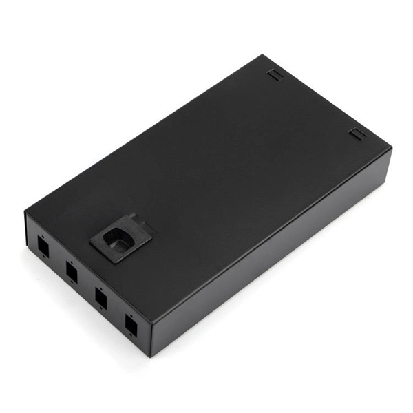
Extending the length of communication optical cables
Yes, fibre optic cables can be extended by using splice closures or optical connectors to join multiple cables together. This allows for longer distances to be covered without loss of signal quality. How do you extend your network? If you get your hands on a Pre-terminated Fiber Optic Assembly and a couple of Media Converters, you're only a few steps away from. In the design of any network—whether a home Wi-Fi setup, an office backbone, or a global telecom infrastructure—the maximum length of network cables is a make-or-break factor. This. The 50-ft limit starts when the cable exits the IMC or RMC conduit. Extending the entrance point with IMC or RMC is a useful provision in applications when it is not practical to have the entrance facility on a ground floor or adjacent to the exterior of the building.
-
How to calculate optical attenuation in communication optical cables
Optical attenuation compares input and output power on a logarithmic scale. When powers are in linear units, the loss in decibels is: Attenuation (dB) = 10 × log10 (Pin / Pout) If the link length L is provided, the attenuation coefficient is: Coefficient (dB/km) = Attenuation (dB) / L (km) For dBm. Signal attenuation refers to the progressive loss of signal strength as it propagates through a medium—whether free space, coaxial cable, or twisted pair. Use this Optical Fiber Attenuation Calculator to calculate total signal power loss through fiber optic cables using fiber length, attenuation coefficient, connector count, and splice count. Getting this right matters in telecommunications infrastructure, data center interconnects, and submarine. Explore the attenuation formula in optical fibres, factors affecting signal loss, and an example calculation for network efficiency. You can apply this methodology to all types of optical fibers in order to estimate the maximum distance that optical systems use. There are no specific requirements for this document.
[PDF Version]
-
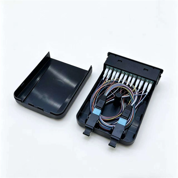
Minimize the number of joints in optical fiber communication cables
When configuring the disk, try to make the entire disk configuration (single plate ≥ 500 meters) to minimize the number of joints. Optical fibers can be joined together, such that light is efficiently transferred from one fiber to another. That is usually done for permanent connections, but it. Fiber optic joints or terminations are made two ways: 1) splices which create a permanent joint between the two fibers or 2) connectors that mate two fibers to create a temporary joint and/or connect the fiber to a piece of network gear. Mechanical splicing involves physically. The handbook provides guidelines for the jointing of optical fiber cables, emphasizing the importance of effective jointing techniques to minimize signal loss.
-
Applications of ADSS optical fiber cables
AFL-ADSS® (All-Dielectric Self-Supporting) fiber optic cable is a non-metallic cable which supports its own weight without the use of lashing wires or messenger cables, typically installed in overhead applications along power distribution or transmission rights-of-way. In the realm of aerial fiber optic infrastructure—where cables must withstand harsh weather, high voltages, and mechanical stress— ADSS (All Dielectric Self-Supporting) fiber optic cables stand out as a game-changer. The self-supporting idea is literal here. The result is that they can be hung in a straight line between poles or towers with no additional metallic. One such innovation is the ADSS cable, a fiber optic solution designed to meet the demands of modern networking while providing exceptional performance and reliability.